The professional video industry's #1 source for news, trends and product and tech information. Sign up below.
You are now subscribed
Your newsletter sign-up was successful
When I write about antennas, readers respond with questions on specific antennas or ask how the antennas I’ve described work (I still get email messages asking about the Gray-Hoverman and UHF rhombic antennas I wrote about two decades ago!). This month, I’ll review some antenna basics that will help you evaluate any antenna, although I doubt any readers are fooled by antenna ads claiming over 100-mile reception. Measurements are great, but an understanding of how antenna elements work will help to evaluate designs just by looking at them!
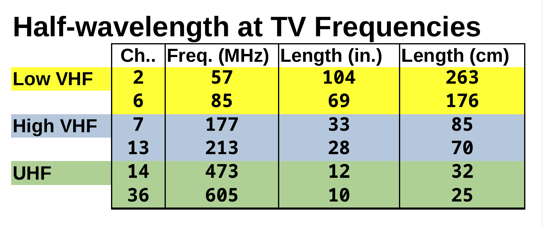
Size is important, but the correct size for the TV-frequency band is most important. The simplest antenna is a half-wave dipole, and when looking at any antenna—transmit or receive—you should see dimensions close to a half-wavelength at the lowest frequency of interest.
Table 1 (next page) shows the free-space half-wavelength at the upper and lower edges of the VHF and UHF TV bands. The element’s actual half-wavelength will be affected by surrounding elements. In a band, the antenna’s active element, the one connected to the coax or balun, should be close to half a wavelength. Combination VHF/UHF antennas will have multiple active elements to cover different bands.
Impedance match for receive antennas isn’t nearly as critical as it is for transmitting antennas, but it will impact signal level, particularly with a long cable between the antenna and the amplifier or tuner. Notice the difference in wavelength in each band. Ideally, the antenna will provide a reasonable impedance match across the TV channels. In addition to size, this is an area in which a look at the antenna can provide some clues.
Shape Matters, Too
At UHF frequencies, a fan dipole, like those seen on bow-tie antennas, will work over a wide frequency range. Decades ago, I made a test antenna to evaluate radiated TV third harmonics using a fan dipole made from copper-clad PC board. While a solid element is best, broadband TV antennas typically use a wire bow-tie or something similar. Larger diameter or thicker elements have a wider bandwidth than thin rods. New designs will have UHF active elements optimized for the post-repack UHF band from 470 to 608 MHz.
Elements with different lengths can be connected to increase bandwidth. Log-periodic antennas do this and offer excellent bandwidth. The “Silver Sensor” indoor antenna, popular when DTV broadcasting started, is one example. You’ll sometimes see multiple dipoles connected to improve VHF performance in an antenna. Note that in these cases I’m talking about active antenna elements—ones connected to the coax or matching network, not the directors or reflectors in front of them.
What about those directors and reflectors? A perfect reflector behind the active elements should double the signal into the element. For a TV antenna covering the entire UHF band, a single rod reflector isn’t going to be as effective as a screen with multiple rods or a wire grid.
The professional video industry's #1 source for news, trends and product and tech information. Sign up below.
Directors—the elements in front of the active element—act as a lens to focus more signal into it. Many directors can be added in front of the active element to improve gain, but as gain increases, bandwidth decreases. For TV antennas, this makes it difficult to obtain significant gain over the entire UHF band with a large number of directors.
The gain of an antenna is directly related to its directivity or beamwidth. When evaluating antennas, do not include gain from amplifiers. A high-gain antenna will require more careful aiming and could be a problem if the TV stations to be received are not in the same location. Gain can be achieved by reducing the azimuth (side-to-side) or elevation beamwidth (up-to-down) directivity. Receive antennas will reduce both to achieve higher gain. Most gain in high-power TV transmitting antennas comes from a narrow elevation beamwidth.
Let’s use some antennas to illustrate these points.
Real-World Examples
An example of an antenna that depends on the reflector for gain is the Scala Paraflector. These are used at frequencies from 450 MHz to over 900 MHz for both reception and transmission. The PR-TV operates in the UHF TV band and has over 16 dB gain at channel 36. It’s a simple antenna, with only two elements in front of the reflector and a very narrow beamwidth. It also has a narrow bandwidth so the desired frequency needs to be specified when ordering the antenna.
Channel Master claims a gain of 12 decibels for its 8-bay “EXTREMEtenna 80” bow-tie antenna. This number appears to be the sum of 9 dB from the 8 active elements and 3 dB from the reflector. The basic design is simple (broadband elements and a reflector) so performance shouldn’t vary much over the UHF TV band.
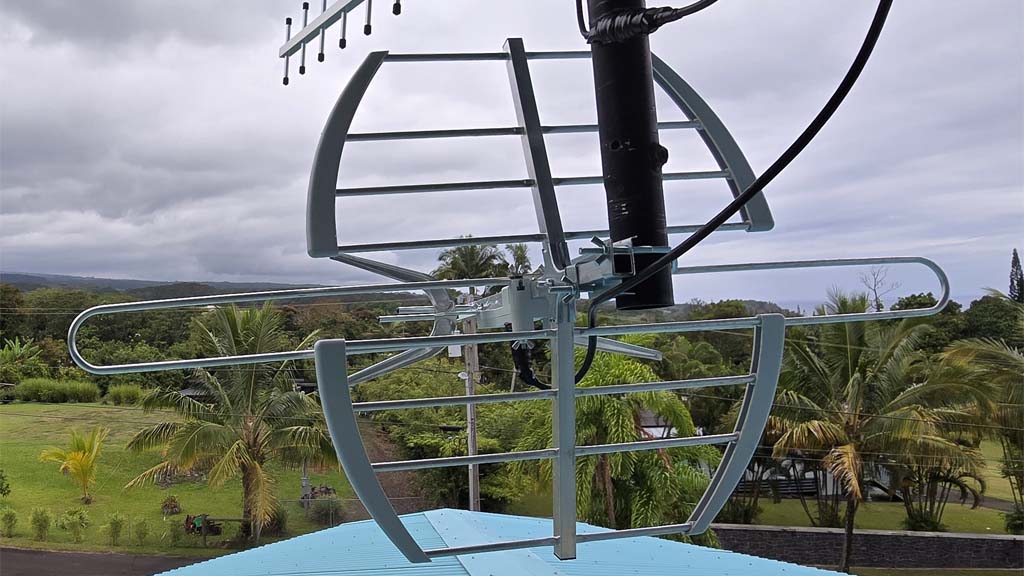
A low-cost TV antenna that’s widely available is the RCA ANT705E and, at less than $50, it performed impressively. As you can see from the image, it has a curved reflector and a wider active element shaped like two horseshoes to cover the UHF band. There are only two directors.
Using our size criteria, the only element that will be significant at VHF is the large folded dipole in front of the reflector. The UHF active element may help a bit as a VHF director, VHF but I doubt the reflector will have much impact. I no longer have my Los Angeles apartment for testing antennas over a wide range of channels, so I was unable to evaluate VHF performance.

The Televes Ellipse Mix is an excellent antenna that costs significantly more but worked well in a difficult environment (see slide 24 in the PDF here). It has a broadband UHF active element. Like the Paraflector and the RCA antenna, there is also a shaped UHF reflector. Unlike the RCA, Televes added a reflector for VHF at the back of the antenna. Rather than use a long boom with director elements in a row, Televes has three levels of directors arranged to focus energy from the upper and lower directors into the UHF active element.
The active UHF elements on both the RCA and Televes antennas don’t taper to a point at the center like traditional bow-tie antenna elements. Elements no longer have to work up to channel 69 (806 MHz), so having more area at the lower channels improves performance.
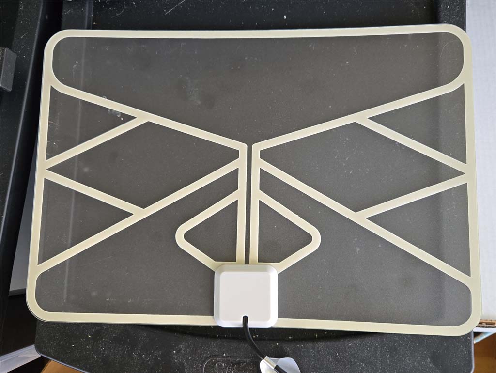
What about indoor antennas? The flat antennas made with copper film on a plastic sheet are easier to stick in a window than the ANT705E. I did some limited testing comparing the Walmart Onn Indoor High-Quality Clear HDTV Antenna with the RCA ANT1120E and Best Buy “Essentials Ultra-Thin” antennas. As expected, the larger RCA antenna provided the strongest signal and the smaller one from Best Buy was the weakest. At UHF channel 36, the difference wasn’t huge. The Onn antenna, at under $25, is the cheapest and the one I’ve been using while traveling.

Doug Lung is one of America's foremost authorities on broadcast RF technology. As vice president of Broadcast Technology for NBCUniversal Local, H. Douglas Lung leads NBC and Telemundo-owned stations’ RF and transmission affairs, including microwave, radars, satellite uplinks, and FCC technical filings. Beginning his career in 1976 at KSCI in Los Angeles, Lung has nearly 50 years of experience in broadcast television engineering. Beginning in 1985, he led the engineering department for what was to become the Telemundo network and station group, assisting in the design, construction and installation of the company’s broadcast and cable facilities. Other projects include work on the launch of Hawaii’s first UHF TV station, the rollout and testing of the ATSC mobile-handheld standard, and software development related to the incentive auction TV spectrum repack. A longtime columnist for TV Technology, Doug is also a regular contributor to IEEE Broadcast Technology. He is the recipient of the 2023 NAB Television Engineering Award. He also received a Tech Leadership Award from TV Tech publisher Future plc in 2021 and is a member of the IEEE Broadcast Technology Society and the Society of Broadcast Engineers.

