The professional video industry's #1 source for news, trends and product and tech information. Sign up below.
You are now subscribed
Your newsletter sign-up was successful
In my column last month (“Get Ready for ATSC 3.0, But Don’t Ignore 1.0”), I compared ATSC 1.0 and ATSC 3.0 reception. While it is being rolled out, ATSC 3.0 is likely to require similar antennas to those currently used for ATSC 1.0 since signal-to-noise requirements are likely to be the same. I received some email from readers who complained that even though they had sufficient signal strength for ATSC 1.0 reception, multipath was a problem, and they were looking to ATSC 3.0 to fix that. In this column, I’ll show how ATSC 3.0 handles multipath differently than ATSC 1.0 and also look at some other features in ATSC 3.0 that broadcasters can use to improve reception.
MULTIPATH AND SPEEDING TRAINS
Multipath occurs when multiple copies of the same signal reach the receiver. These copies could be from other transmitters in a distributed transmission system (DTS) or, more likely today, from reflections from other objects. These objects include stationary objects like buildings and bridges and moving objects like trucks and airplanes. The impact of multipath on reception depends on the difference in time and the difference in signal level between the signals.
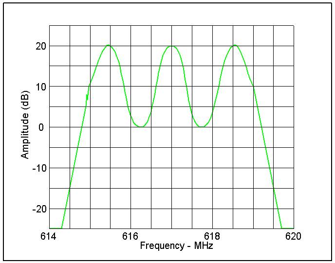
ATSC 1.0 is a single carrier transmission system. One 8VSB carrier has to carry the ATSC data rate of 19.392 Mbps. Multipath is visible on a spectrum analyzer as ripple (Fig. 1) in the 8VSB spectrum. By measuring the ripple it is possible to determine the time difference between the signals creating the multipath. (See my Jan. 1, 2000 article “Comparing 8VSB and COFDM for DTV Broadcasting” for details on how to do this. Fig. 1 is missing, but is the same as Fig. 1 here.)
ATSC 1.0 receivers deal with multipath using adaptive equalizers. In the simplest sense, an adaptive equalizer digitally stores copies of the incoming signal and shifts them in time to cancel out the multipath. As a result, the range of multipath delays and signal levels an ATSC 1.0 receiver can handle is dependent on how much the receiver manufacturer is willing to spend on the equalizer. The “coupon-eligible” DTV converter boxes sold during the analog-to-digital transition had to meet certain standards, but those do not apply to TV sets sold today. This variability in receiver performance makes ATSC 1.0 DTS design difficult.
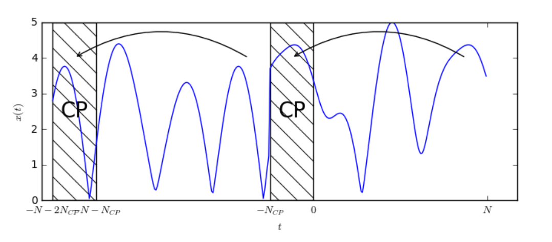
With ATSC 3.0’s OFDM, multipath performance is controlled by the broadcaster. In OFDM, the data is divided among thousands of carriers so each carrier has to carry a much smaller amount of data. Multipath appears as interference between OFDM symbols; ATSC 3.0 handles multipath by inserting a guard interval between symbols. The guard interval (GI) is created in the time domain by taking samples belonging to the last part of the OFDM symbol and prepending them as a cyclic prefix to the original symbol.
This extra information allows the receiver to fill in the information lost due to multipath. ATSC 3.0 offers 12 selections of GI sample size. The relationship between the number of samples and the allowable time difference between multipath signals depends on the number of carriers as explained in my Jan. 1, 2000, article.
For a detailed explanation the cyclic prefix and how it works, look up “The Cyclic Prefix for OFDM” at dspillustrations.com. This website also offers a digital communications tutorial using a computer sound card for hands-on experience. Fig. 2, which shows how the cyclic prefix is generated, is from this website.
The professional video industry's #1 source for news, trends and product and tech information. Sign up below.
The use of OFDM in ATSC 3.0 doesn’t eliminate the need for an equalizer to remove distortion in the signal caused by multipath or frequency response variations in the receive system itself. The ATSC 3.0 standard has pilot carriers with known characteristics that can be inserted at regular and scattered intervals in frequency and time to make equalization easier. More pilot carriers will make it easier to lock on the channel with varying multipath.
Adding guard interval reduces usable symbol time and adding pilots reduces the number of carriers available for data. The optimum guard interval depends on the maximum multipath time difference. Testing of ATSC-MH (mobile-handheld) in the San Francisco area found a very long echo from the San Francisco-Oakland Bay Bridge caused reception problems in some areas—a long guard interval would fix that. When multiple transmitters are used in a DTS, the spacing of the transmitters and the signal overlap will determine the guard interval required. The ONEMedia App (see details later) will provide the guard “distance” for a given system configuration.
There is another element to multipath, which I did not mention earlier—Doppler. Doppler is the change in frequency as an object moves towards or away an observer, (as with a train whistle increasing in pitch as it approaches and decreasing as it moves away). 8VSB performance with Doppler was poor and varied by receiver, resulting in some viewers losing reception due to reflections from planes passing overhead.
Reflections with Doppler can cause loss of an OFDM signal as well, but the standard offers options to deal with it. Earlier, I mentioned OFDM divides the data among many carriers. The FFT size options are 8K, 16K and 32K, roughly corresponding to 6,900, 13,800 or 27,600 carriers. A larger FFT size is more efficient, but because the carriers are spaced closer together it will be more susceptible to Doppler. An 8K FFT is most robust, allowing mobile reception at any terrestrial speed likely to be found in private or public transportation, at least in the United States.
The impact of reflections, either as static multipath or as Doppler, once outside the range of the FFT or guard interval to handle it, is the same as noise. As a result, a robust signal with a lower SNR (signal-to-noise ratio) requirement will be less affected by multipath or Doppler. One way to take advantage of this is to use an FFT of 16K with LDM. While the robust LDM layer will experience more Doppler interference with the 16K FFT, if the required SNR is much lower, it can still work in many mobile environments while preserving the benefit of a 16K FFT for the enhanced layer.
IMPULSE NOISE
One problem that has plagued ATSC 1.0 reception, especially at VHF, is impulse noise. ATSC 1.0 has a data interleaver to spread data over time to reduce the impact of brief signal loss, but that time is limited to a small fraction of a second. ATSC 3.0 has three time interleaver modes: None, Convolutional Time Interleaver (CTI) and Hybrid Time Interleaver (HTI). Extended Time Interleaving (ETI) is available for physical layer pipes (PLPs) using QPSK.
The length of the interleaving depends on how the ATSC 3.0 PLP is configured, and can be much larger than that available with ATSC 1.0. With so many options, it will likely take extensive field-testing at VHF (perhaps including low VHF) to determine what configurations work best. Using CTI and HTI should not impact data capacity, but the longer the time interleaving, the greater the latency.
ATSC 3.0 also includes a frequency interleaver, which would aid in reception in the event a single carrier or group of carriers was interfered with or otherwise lost.
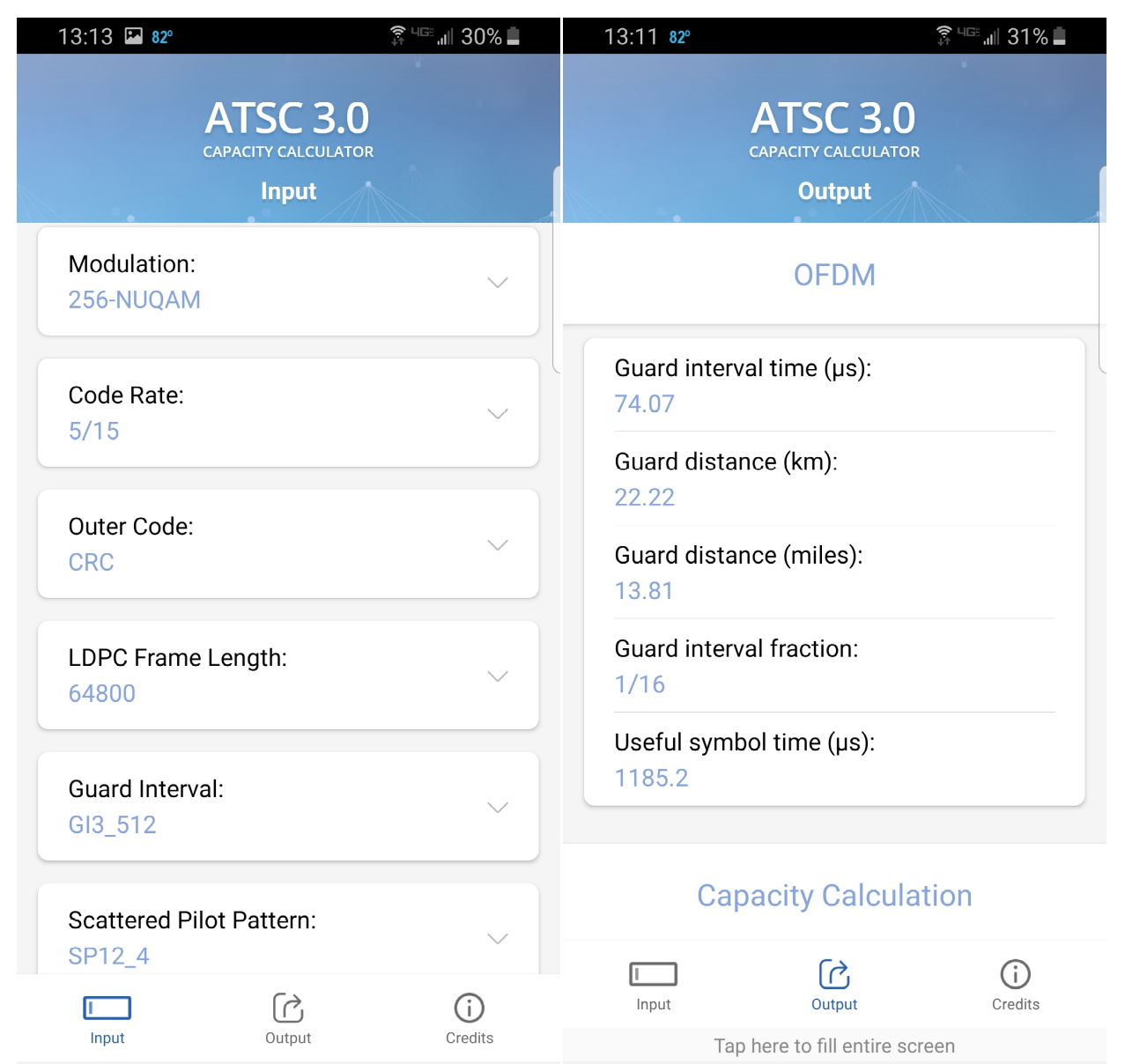
To learn more about the options available in ATSC 3.0, see ATSC Recommended Practice A/327, “Guidelines for the Physical Layer Protocol,” available from the ATSC web page under “Recommended Practices.” To play around with the options, ONE Media (the Sinclair company focused on ATSC 3.0), has created the app “NextGen TV Calculator” to determine channel capacity and performance of an ATSC 3.0 signal with different configurations, including guard interval. Visit onemediallc.com for IoS and Android download links. Fig. 3 shows a sample of the input and output from the ONE Media app on Android. The input and output data extends above and below what’s shown in the screenshot. The output, for example, includes final required SNR under Gauss, Rice and Rayleigh channels for the configured input.
I welcome your comments and questions on ATSC 1.0, ATSC 3.0 or broadcast RF technology in general. Email me at dlung@transmitter.com.
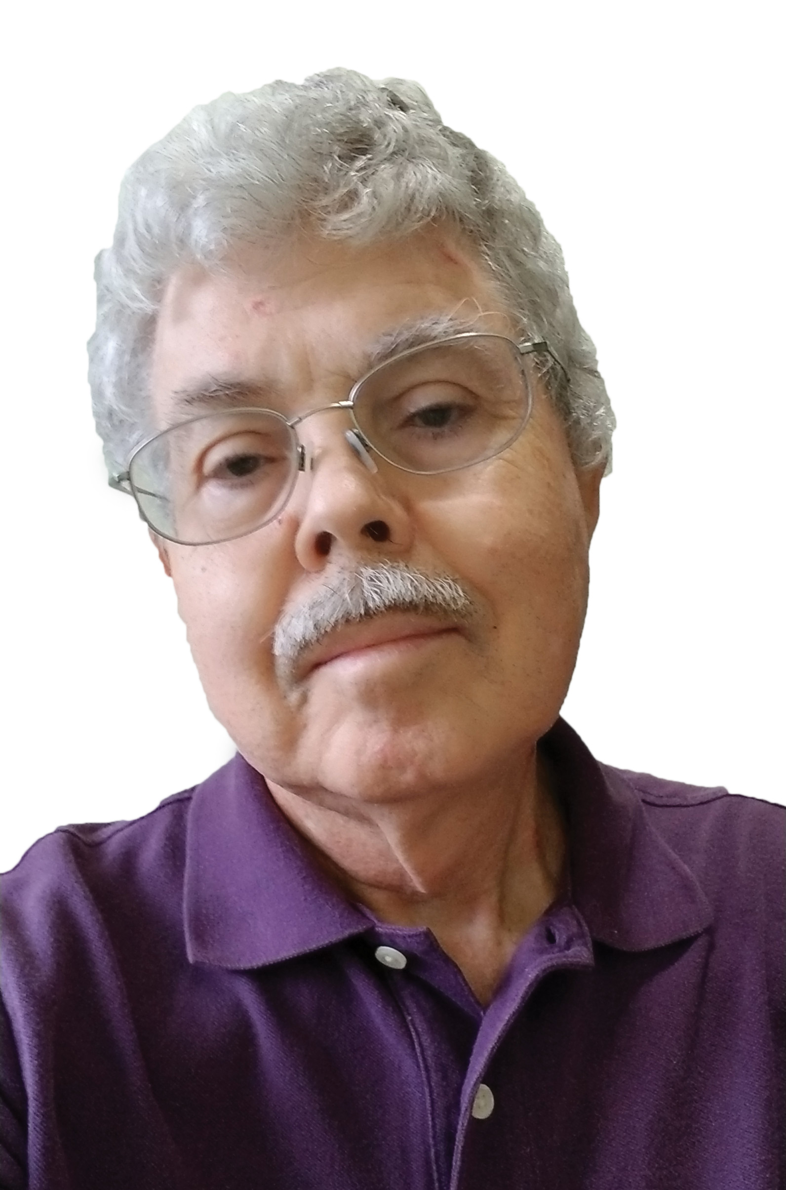
Doug Lung is one of America's foremost authorities on broadcast RF technology. As vice president of Broadcast Technology for NBCUniversal Local, H. Douglas Lung leads NBC and Telemundo-owned stations’ RF and transmission affairs, including microwave, radars, satellite uplinks, and FCC technical filings. Beginning his career in 1976 at KSCI in Los Angeles, Lung has nearly 50 years of experience in broadcast television engineering. Beginning in 1985, he led the engineering department for what was to become the Telemundo network and station group, assisting in the design, construction and installation of the company’s broadcast and cable facilities. Other projects include work on the launch of Hawaii’s first UHF TV station, the rollout and testing of the ATSC mobile-handheld standard, and software development related to the incentive auction TV spectrum repack. A longtime columnist for TV Technology, Doug is also a regular contributor to IEEE Broadcast Technology. He is the recipient of the 2023 NAB Television Engineering Award. He also received a Tech Leadership Award from TV Tech publisher Future plc in 2021 and is a member of the IEEE Broadcast Technology Society and the Society of Broadcast Engineers.
