Acoustic Design for Multichannel Audio Control Rooms
As the shift to 5.1 and beyond surround sound mixing rooms continues—with the potential for immersive audio on the horizon—there have been some new thoughts on the internal acoustical design. The ultimate goal of providing a neutral listening environment where critical judgments can be made on the quality of sound sources and the overall mix doesn’t change. Where the rethinking comes in is how to handle the internal sound field to accomplish this goal. So, all the usual suspects of good design—solid construction, adequate room volume, low-frequency modal control, symmetry, noise and isolation control, loudspeaker choice and placement and mix position placement—still apply. I’ve covered these topics in the past, and they have recently been revisited by my TV Technology colleague, Jay Yeary (Exploring Audio Control Room Acoustics).
THE RFZ CONCEPT
Since this new approach builds on current best practices, a brief review may be helpful. Ever since the concept of Live End- Dead End control room design emerged in the late 1970s, the idea was to keep early reflections away from the mixing position by making the front end of a control room absorptive and the rear diffusive. This concept was soon expanded and enhanced by thinking of a reflection-free zone (RFZ) around the mix position.
Absorption, while effective in controlling reflections, could end up creating a “dead” sounding environment, especially if too much was used. The RFZ was achieved not only by properly specified and situated absorption, but in the room geometry with splayed walls re-directing sound energy away from the mix position to the diffusive rear wall or walls. If the angles were correct, the splayed walls could actually be reflective, thus keeping more sound energy in the room.
At the same time diffusor science and technology took a giant leap forward in the early 1980s with the introduction of the Quadratic Residue Diffusor (QRD) by Dr. Peter D’Antonio and the company he cofounded, RPG Diffusor Systems Inc.

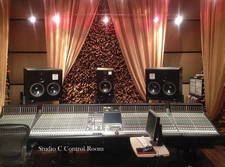
Studio C control room at Blackbird Studio Using diffusor concepts based on number theory as advanced by Manfred R. Schroeder, it was possible to predict how sound would scatter upon hitting the diffusor. This allowed for the design of units that provided more uniform scattering of sound in space and time within the designed frequency range than other forms of diffusion, such as poly-cylinders or pyramid shapes common in use at the time. (Since the QRD, there have been further diffusion improvements by RPG.)
Timing and the control of the diffuse sound level factored into the RFZ concept. Measurements, experimentation and the latest research on human sound perception and localization indicated that about a 20-millisecond time difference from the arrival of the direct sound from the loudspeakers to the first reflections would be needed to create an RFZ. This meant that the zone was effectively anechoic (without echoes or reflections) during this time period.
To keep the room from being a truly anechoic space—which is very unnatural for listening—broadband diffuse, rather than specular, reflections would be allowed to arrive at the mix position after about 20 milliseconds. The level of this diffuse field would be quite a bit lower than the direct sound, around 30 dB, and decay fairly evenly over time. The QRDs, new at that time, provided this type of diffusion in a small space.
The professional video industry's #1 source for news, trends and product and tech information. Sign up below.
This level and spacing of diffusion didn’t interfere with the ability to critically evaluate the direct sound. Properly implemented, a control room with an RFZ provided good stereo imaging, and not necessarily in just one “sweet spot,” but across the width (or a good part) of the mixing console.
LEDR TEST SIGNALS
Imaging was not necessarily relegated to just the lateral plane. A test tape called LEDR, a trademarked acronym for Listening Environment Diagnostic Recording developed by Doug Jones, contained a series of specially designed synthesized and filtered sounds. When played back in a well-designed RFZ room over a pair of loudspeakers, these sounds would appear to travel not just left to right, but up, over and behind the listener in the RFZ.
These synthesized sounds simulate reflections off the pinna of the ear (the outer ear) combined with direct sound. This results in comb filtering in the frequency response. As sound moves around a head, the comb filters change, providing auditory cues as to location. This was brought to the audio community’s attention by Dr. Carolyn “Puddie” Rodgers in the late 1970s and early 1980s.
(There are other auditory localization cues that include level, phase and time of arrival differences between the two ears.)

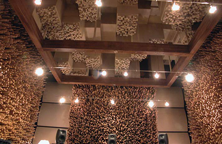
Front and ceiling diffusive surfaces at Blackbird Studio The LEDR test signals are now online at www.audiocheck.net/audiotests_ledr.php. The effects can be heard on headphones and downloaded to check out a room. In a control room situation, if early reflections interfere with the direct sound, especially within the first 20 milliseconds of arrival, then the resultant comb filters can conflict with pinna localization cues, and the effects on the LEDR recordings won’t be heard.
The RFZ concept (and the LEDR test sounds) was developed in the age of stereo recording and monitoring. Could there be improvements for multichannel audio control rooms?
There are proponents of eliminating the reflection-free zone and instead create an overall diffuse sound field throughout the room, including the mixing position. There are different opinions as to the level and characteristics of this sound field so that the ability to critically perceive the direct sound isn’t hampered.
One recording studio put this concept into practice: Studio C of Blackbird Studio in Nashville, Tenn., which was designed by noted recording engineer, producer and audio equipment designer George Massenburg who collaborated with RPG on this project.
Studio C, based around a Digidesign ICON, has wide-bandwidth diffusive surfaces on all walls and ceiling. But these aren’t garden-variety off-the-shelf diffusors.
The large-scale, wide-bandwidth, two-dimensional diffusors were custom-designed and fabricated from a series of one-inch square (in cross-section) block pegs—each one a different height—that stick out from the wall in a specific arrangement. Over 130,000 different peg heights, with no two the same, were used to create the diffusive surface. The room treatment also included diffractals on the ceiling and low-frequency resonators (dampened metal plates).
The diffusion this treatment creates is very dense, with a level around 30 dB below that of the direct sound, and an even decay rate over time.
RPG is calling this concept “Ambechoic,” a trademarked name for ambient anechoic. The room as a whole has ambient energy due to the extensive wide-band diffusion, but at the mixing position it’s reported that there’s precise imaging and an extended “sweet” zone. In addition, monitoring can be done at lower levels.
Why does this work? It seems more research needs to be done, but the ear/brain integration time may play a pivotal role.
Studio C is a fairly large mixing room at more than 24,000 cubic feet, so the space was available to accommodate the diffusive surfaces with some of the elements sticking out more than three feet from the wall.
According to D’Antonio, “The Ambechoic design is really intended for larger rooms than broadcast because you have to develop low-level diffuse reflections, which is difficult when close to a boundary. 2D diffusors are also necessary to omnidirectionally distribute the energy. The idea is to provide a uniformly diffuse environment.”
Could this concept be adapted for smaller control rooms? It’s something to think about; and it will be interesting to see how this develops further as designers explore the possibilities.
Mary C. Gruszka is a systems design engineer, project manager, consultant and writer based in the New York metro area. She can be reached via TV Technology.
