AES Standardizes Application of 25-Way D-Type Connectors
MARY GRUSZKA As audio systems designers, much of our work involves generating cable run sheets, looking up connector pinout information, and generally making sure that one piece of gear can physically connect to another.

With multi-pin connectors especially, we often find different manufacturers’ pinout strategies differ from one another, even with the same style of connector.
So it was encouraging to see that the Audio Engineering Society has tackled the pinout standardization of one of the more common multi-pin connectors used for audio, the D25 25-pin subminiature Dconnector.
The standard is AES59-2012, “AES standard for professional audio - Audio application of 25-way D-type connectors in balanced circuits,” published August 18, 2012.
“Over the past several decades, there have been many interesting, yet incompatible, ways to use the widely available 25-way D-type connector in audio applications,” said Mark Yonge, AES Standards manager. “This standard was instigated by Steve Drummond of SSL who felt that a single standard specifically for balanced audio circuits—both analog and AES3 digital— would save everyone a lot of time and effort by making specialized interconnections and patch cables unnecessary.”
Steve Drummond, technology development manager of Solid State Logic, added, “It was originally inspired by an email conversation four years ago with Graham Hinton of Hinton Instruments complaining about the difficulty of connecting one of our pieces of equipment to another manufacturer’s.”
PINOUT ASSIGNMENTS
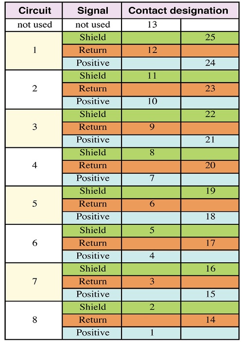
Among its provisions, this standard provides the pinout assignments for eight pairs of analog or digital (AES3) audio circuits in one D25. This is listed in Table 1, and an illustration of the physical layout is shown in Fig. 1.
The professional video industry's #1 source for news, trends and product and tech information. Sign up below.

Table 1: 25-contact subminiature (D-SUB) connector assignment for balanced audio per AES59-2012—Inputs or outputs, analog or digital (analog and digital not mixed, analog inputs and outputs not mixed, see Fig. 1 for mixed digital inputs and outputs). Chassis connector is DB25F (female), cable connector is DB25M (male).
NOTE 1 While this contact arrangement will be satisfactory for either analogue or digital signals, practical performance with digital signals may depend on using an appropriate cable type. See AES3-4-2009 and AES-2id.
NOTE 2 AES3 digital interconnections are not polarity sensitive. However, maintaining consistent polarity in all connectors permits digital cables to be used with analogue circuits if the need arises.
“The pinout was based on one of the two defacto ‘standards’ that were and are in use—the pinout that Tascam used for the analog connections on the DA-88 recorder,” Drummond said. “Unlike the other common pinout based on the Yamaha I/O cards, [the Tascam] has a separate shield connection for each signal and is laid out with each channel on adjacent pins, making it easier to terminate. A number of manufacturers were already using the ‘Tascam’ pinout.”
According to the standard, a single D-25 connector can be used for eight analog inputs or outputs, or eight digital inputs or outputs, but not mixed analog and digital, nor mixed analog inputs and outputs.
“Mixing analog and digital signals would risk, and probably guarantee, cross talk from the digital to analog signals,” Drummond said.
The standard does provide a pin-out for a mix of four digital inputs and four digital outputs on a single connector, as shown in Fig. 1.
“Originally we proposed that the AES-3 ‘digital’ connector would always be I/O, but some members of the committee felt this was too restrictive. For example, a 16-channel AES-3 input card would have required two connectors,” Drummond said.
The standard states that “equipment using this alternative shall be clearly labeled.” But the nature of this labeling is under ongoing consideration according to Yonge, and as he said, “is expected to be addressed in an amendment to AES59.”
With the D-25 pinout as shown in Fig. 1, “the signal conductors and shield (screen) contacts all have the same geometrical relationship and so it should be possible to implement wiring and PCB track layout such that the EMC emissions and immunity associated can be as low as possible and the same for all channels,” Yonge said.
This was an important consideration, as the SC- 05-02 working group, the group within the AES standards committee that is tasked with connector standards, wanted to ensure that “cable shields … needed to be connected correctly and consistently to avoid the ‘Pin 1’ problem outlined in AES48 and AES54, and to optimize EMC and shielding performance in an increasingly dirty RF environment,” Yonge said.
CONNECTOR GENDER
As for the gender of the connectors, cables are male to male with the female connectors mounted on equipment chasses.
The gender of the connector was set from the start, Drummond said, “largely because that was what Tascam did and this convention had been copied by a number of other manufacturers. From a practical point of view it made sense to have the more vulnerable connector on the cable [as] it’s cheaper and easier to change a cable end.”
D-25 connectors come with jackscrews to secure the cable connector to the chassis connector. However, there are different thread sizes in common use. The standard recommends the use of jackscrews with the 4/40 thread.

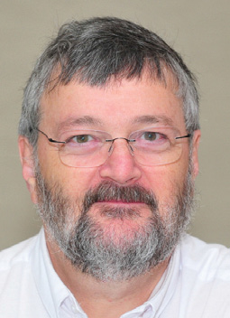
Steve Drummond “The jackscrew recommendation was felt to be necessary because of the noncompatible jackscrews for D-type connectors encountered in the field,” Yonge said. “The reference standard, IEC 60807-2, permits either the unified inch thread 4/40, or the metric M3 thread, but these aren’t mutually compatible. The group also learned of other thread sizes in use, including 2.6 mm. Jackscrew incompatibility doesn’t help when the intent is to connect equipment and have it stay connected. The jackscrews really should work.
Accordingly, we added the recommendation, a requirement would not have been practical, for the 4/40 thread as the size most commonly encountered by our members.”
The process to develop this standard started in early 2009. “The discussion that followed was fairly intense, at least partly because so many people had been using D-type connectors for audio over many years that the detailed folklore tended to obscure the goal of a simple, sensible standard,” Yonge said.
Now that the standard is published, and hopefully will be generally adopted, “It will become easier for professional audio users, exemplified by the AES membership, to specify and connect audio equipment with fewer last-minute surprises,” Yonge said. “Rental equipment is an obvious candidate for standardized connections, but cabling audio components in fixed and temporary installations will also benefit.”
Mary C. Gruszka is a systems design engineer, project manager, consultant and writer based in the New York metro area. She can be reached via TV Technology.
