Testing for DTV Interference

A colleague of mine, Linley Gumm and I have just completed a set of interference measurements to 10 NTIA-approved DTV downconverters.
We were concerned that powerful FM radio signals between 88.1 and 107.9 MHz might pass through the rather limited RF selectivity of modern DTV tuners at levels that would overload the mixer, thereby generating second order distortion products that just happen to fall in the 174–216 MHz High VHF Band.
Before I reveal our findings, a little background is in order.
Any active device, amplifier or mixer will generate second order distortion products given that the input signal voltage overloads the active device. There are two second order distortion products, one you know well from audio: second harmonic distortion, and the other you know from the fundamentals of superheterodyne receivers mixing. There we have a signal at some frequency Fs and it is mixed with a much stronger Local Oscillator at a frequency Fo.
In radios, Fo was always 455 kHz above Fs so the useful mixing product was Fo – Fs = the IF frequency, nominally 455 kHz. But there are two such mixing products, the other is Fs + Fo, which in the case of radios was filtered out. That example was for a simple AM receiver.
Now fast forward to two FM radio signals at say 90.7 MHz and another at 92.1 MHz, which reach the mixer. The mixer output will contain 181.4 MHz and 184.2 MHz components, which are the second harmonics of these FM signals. Both land in Channel 8 (180 – 186 MHz).
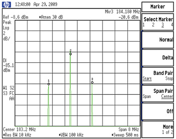
There will also be what I call the Sum frequency: 90.7 MHz + 92.1 MHz = 182.8 MHz, which is also in Channel 8, but this one is 6 dB stronger than either second harmonic. This is shown in Fig. 1 of the spectrum of these second order distortion products of two FM band signals.

Fig. 1: Second order distortion products of two FM band signals, 90.7 and 92.1 MHz In Fig. 1 the scale is 2 dB per major graticule division, so it is clear that the Sum frequency is 6 dB stronger than the second harmonics. In this example all three second order distortion products fall in the same channel.
Now consider this example: F1 = 88.5 MHz and F2 = 107.3 MHz. The second harmonic of F1 lies within Channel 7, that of F2 lies in Channel 13 while their Sum = 195.8 MHz in Channel 10.
You must be thinking that if this is true, why don't we have interference from FM signals in analog TV receivers?
FM Traps
The answer is that this interference mechanism was well understood when the FCC planned the post-World War II VHF spectrum in 1944. And so did the receiver manufacturers who were able to provide enough RF selectivity before the mixer that this interference mechanism was not too much of a problem.
But because some viewers might live quite near FM transmitters while the TV towers were located elsewhere, sometimes on mountain tops, the better receiver had FM traps, which attenuated FM band signals before they ever reached the tuner. Such FM traps were described in K. Blair Benson's "Television Engineering Handbook" in the chapter on TV receiver design.
When the nation's major markets got "cabled" a large majority of viewers began to obtain their television reception from a CATV system, with all signals being maintained a level above visible noise, and below the overload level. This greatly reduced or eliminated the need for FM traps in receivers and as a result they vanished from later models.
So why am I telling you all this?
In one word: "Digital." DTV receiving appliances (receivers, downconverters, DVRS) have very small tuners, and in some cases RF selectivity has been sacrificed for compact and low-cost tuners.
The NTIA minimum RF performance specifications were taken from ATSC document A/74, which does not mention interference from any undesired signals other than NTSC and DTV.
No mention of FMI (my term for frequency modulated interference). As a matter of fact, no test for FMI to DTV reception was in the ATSC Test Plan, which was followed rigorously by the ATTC in 1995. Moreover, the FCC Rules concerning DTV do not mention FMI.
So, in far off lands where downconverters are made, they design to the NTIA specifications. Perhaps they believe FCC rules only apply to broadcasters.
We realized that in testing NTIA downconverters, which are small and inexpensive, we could see how downconverters work in the presence of strong FM signals. To the extent that DTV receivers have the same tuners, perhaps we can determine the broader effect of FMI if there is any.
THE PORTLAND PROBLEM
Portland, Ore. has a very large percentage of homes receiving TV service by means of their antennas, rather than via Cable or DBS. Three of our local stations will use their former high band VHF analog channel for DTV, so if there is an FMI problem, it will be here on June 13.
When Congress postponed the end of analog broadcasting it appeared at first that we had no choice but to wait for June 13, on which date our three high band VHF channels would commence DTV broadcasting.
However, we devised a scheme by which laboratory testing could provide information concerning the robustness of DTV downconverters (and probably on DTV receivers too) before June.
Linley Gumm designed and built a high band VHF RF test bed, which augmented my UHF DTV test bed. We now have our answers from laboratory testing of 10 NTIA-approved DTV downconverters.

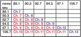
Fig. 2: Examples of FM interference into Channels 7-13 FMI may result when the DTV receiver is near one or more FM stations, hence receiving strong undesired signals while either at a distance from the desired DTV transmitter site, or where there is no direct ray path as behind a hill or large building.
Fig. 2 shows how the second order distortion products generated in a receiver from six strong FM signals are distributed across the high band VHF channels.
Assuming that your post- transition channel is in the high band VHF region, you can analyze your station's situation concerning FMI by mimicking this example. Your table should not include FM stations whose signals are weak. I drew the line at –40 dBm.
Fig. 3 shows our results with the FM signals as received at my home roughly 14 miles or so from the FM towers in Portland.
Their total received power is –26 dBm, some 10 dB stronger than any DTV signal here.
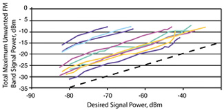
The straight black line below the data plots has a slope of 2:1, which is the slope of second order distortion products. That is for a 10 dB increase in the signal causing the distortion, you get a 20 dB increase in the distortion. In Fig. 3, all of the performance data plots are parallel to this straight line with a slope of 2:1, which confirms that the effect shown is due to second order distortion products.

Fig. 3: Test results for FMI threshold of 10 NTIA-approved downconverters What Fig. 3 also shows, in my opinion, is a large range of robustness between different units tested. For example, at D = –80 dBm the worst unit will not function where the total FM power is greater than –31 dBm, while the best unit will work at –14 dBm.
Near the noise-limited desired signal power (–84 dBm according the FCC) these curves turn downwards because of the combination of receiver-generated noise plus the FMI. At –68 dBm, receiver-generated noise is negligible compared to the FMI so these curves have become remarkably straight. Some, but not all, curve upwards at higher desired signal powers. This is probably due to their RF AGC coming into play.
The good news is that FMI can be eliminated by installing a 75 ohm FM band stop filter at the input to the afflicted DTV receiving appliance. A much lower-cost alternative is a 75 ohm high pass filter (HPF) which attenuates FM signals and any low band VHF DTV signals. In many communities, there will be no DTV signals on Channels 2 through 6, so a high pass filter will work fine. However there are some communities with one or more DTV stations on low band channels. A way around this would be an A/B switch to bypass the HPF when a low VHF band channel is desired.
That is so awkward that most viewers would pay the higher price for an FM band stop filter (if available). However some FM band stop filters may affect DTV reception of Channel 6. Clearly, experimentation is in order.
Stay tuned.
Charlie Rhodes is a consultant in the field of television broadcast technologies and planning. He can be reached via e-mail atcwr@bootit.com.
The professional video industry's #1 source for news, trends and product and tech information. Sign up below.
