Router evolution
Routing switchers are a common element in a wide variety of television production and distribution systems. They provide an efficient, reliable and economical means of connecting signal source devices to the destinations where the signals are used. As the industry has evolved over recent years, from analog through digital and now to HD and higher-resolution systems, routing systems' operating requirements have undergone a similar evolution.
History
Early systems were built primarily to take advantage of a common set of inputs.
Early routing systems essentially were blocks of single-bus switchers tied together to take advantage of a common set of inputs. Control generally was limited to a row of pushbuttons for each output. As systems grew in size from 30 or 40 inputs all the way to 60 or more, it became impractical to continue adding buttons to the control panels. That is when numeric addressing came into use. Operators keyed a source number on a keypad to select the desired source. With the introduction of addressing, it also became practical to create a control panel that allowed operators to select sources and destinations, giving rise to the variety of multibus and full-matrix control panels designed as central router control points for use in studios and master control rooms.
LCD button panels allowed for easy relabeling without removing keycaps — a big advance in flexibility.
The next big advance in user interfaces for routing systems came with the introduction of alphanumeric displays that could present source and destination labels to the operator, eliminating the need for the paper “look-up tables” always taped to the rack next to the numeric panels. A control panel with alphanumeric displays made it easy for non-expert operators to control the router, greatly extending the routing system's utility in streamlining the facility's operations.
Today's router control systems still largely depend on the operational practices developed in the early days of alphanumeric addressing. Because the control panels had a limited number of keys available, labeling systems were designed around the idea of grouping sources and destinations into “categories.” One of the keys in the keypad would access a category, and then a one- or two-digit number would select the desired member of that category. The category-plus-number system made it simple to, for example, select CAM 1 or VTR 22. Then, however, the operator needed to find the old lookup table to figure out that TEST 5 would yield SMPTE color bars. Some systems were able to display a descriptive name after the source was selected, but because the labels on the keys were fixed, users were stuck with a limited set of category names.
The professional video industry's #1 source for news, trends and product and tech information. Sign up below.
This history brings us to the current phase of control-panel evolution — panels with relegendable buttons. The availability of pushbuttons with built-in LCD displays and multicolor illuminations has at last freed us from the restrictions of a limited keypad with fixed labels. Early panels with LCD buttons took advantage of the fact that buttons could easily be relabeled, allowing the system's administrator to change category names, for example, without the need for removing and relabeling the keycaps on every panel. This feature was a big advance in system flexibility, but the button labels essentially were fixed once the system programming was completed, and the panels were operated in the same way as panels with fixed-label keypads.
The latest generation of control panels takes full advantage of the dynamic labeling features of LCD buttons, allowing the panel's buttons and displays to work in a dynamic mode, driven by internal menus in the panel software. This means the category-plus-number labeling system can be left behind at last, replaced by panels that provide unlimited flexibility in grouping sources and destinations into an intuitive and transparent structure for all operators, regardless of their technical training or expertise.
Soft panels
“Virtual” control panels are important now because they can show on all computer, phone and tablet screens.
It is becoming increasingly important in today's facilities for the router control system to provide “virtual” control panels — GUI representations of router control panels that can be presented on the screens of computers, phones and tablets that are all part of the broadcast facility.
A good GUI control panel system will provide a toolbox for designing an unlimited range of on-screen panels, from simple button-per-source panels to panels that support the setup of complex monitor walls. The ability to support multiple operating systems and Internet-browser-based panels can greatly extend the usefulness of the virtual control panel system.
The ability to publish the panels over a network with specific access rights for users or groups of users can also make the system much more useful. Close linkage to the control-system configuration files can make the panel-design process much simpler, allowing the panel to be designed with point-and-click navigation rather than having to type in the source and destination labels as the panel is being laid out.
Advanced control functionality

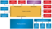
Figure 1. Modern systems have added many features that require various forms of signal processing with the router.
Modern routing systems are adding a number of features that involve various forms of signal processing with the router. (See Figure 1.) An example of this is embedded signal processing, which allows embedded audio arriving on digital video streams at a router's inputs to be extracted, manipulated and re-embedded at the outputs. Controlling these functions requires a new approach to the design of the control system and presents a tremendous challenge in designing a user interface intuitive yet powerful enough to take full advantage of this compelling new ability.
At the same time, external control of the router by automation, scheduling systems, editors and production switchers is increasingly important when it comes to integrating the router into the overall system. Having external control requires the ability of the router control system to communicate with external systems such as tally management, under-monitor display devices, and — with the expanding use of flat-panel-based monitor walls — the external multiview image processor.
Traditionally, communication from the router control system to these external devices has happened through a simple numeric interface. The router status was sent as a message that output XX was connected to input YY, which meant the external system's programming needed to be reconfigured to match the router's labeling configuration every time the router was updated.
In modern systems, it is possible to download the router's programming information directly to the external device, allowing the complete system to be updated automatically when changes are made to the router's configuration.
System configuration
Figure 2. A custom GUI for panel programming can save time during router control system installation.
The most time-consuming part of installing and maintaining a router control system is reprogramming dozens of control panels to reflect the new system configuration. (See Figure 2.) This is where the router control system can make a big contribution by automating repetitive parts of the process. Most systems offer a GUI for panel programming. The best systems allow the GUI to be customized. For example, an operator can create separate “views” of certain parts of the system to reduce on-screen clutter and allow the operator to focus on specific devices.
System monitoring
Once the router system is in operation, the control system must provide a comprehensive toolbox for monitoring its operation. (See Figure 3.) Alarm indicators such as power-supply failure and temperature alerts must be presented in a clear and easily understandable form to the maintenance crew so that corrective action can be taken to avoid service interruptions.
Figure 3. A comprehensive monitoring toolbox is necessary once the router system is operational.
The monitoring/maintenance utility is also the logical place to provide tools for operational supervision, giving access to high-level functions such as tie-line management, identifying and troubleshooting hardware faults, and releasing locks.
In a growing number of facilities, the routing switcher is tied into an overall network management system (NMS). These systems monitor the health of the complete facility by receiving messages from the individual subsystems via SNMP communications. The routing system must be able to provide alarm information via SNMP trap messages, and additional functionality, such as loss of signal (LOS) alarms on critical inputs and outputs, can be very useful to the NMS in tracing the root cause of a service interruption through the various devices in the system.
The future
The increasing sophistication of router control systems has kept pace with the amazing growth of routers over the past few years.
Modern systems are infinitely easier to configure, manage and maintain than their predecessors, making it more practical to design systems based on a large, central routing switcher. In the future, we can look for the router to become even more tightly integrated into the facility, providing an expanding range of functionality that traditionally has been handled by dedicated equipment.
Control systems will expand to keep up with these added functions, while making the overall system operation more efficient. All of this will streamline workflow while expanding flexibility.
Scott Bosen is the director of marketing for Utah Scientific.
