At the 2012 NAB Show I saw three transmitters on display that promise solid-state amplifier efficiencies matching those of IOT (Inductive Output Tube) amplifiers. Although solid-state amplifiers offer inherent redundancy (higher reliability) and easier maintenance (no multi-kV power supplies) they weren’t able to compete with IOT devices in terms of cost and efficiency at power levels much above 10 kW, although the 50-volt LDMOS solid-state amplifiers come close.
The new Screen Services, Rohde & Schwarz and Thomson transmitters should be capable of meeting or exceeding IOT amplifier efficiency on a total-plant efficiency basis, but it doesn’t appear they will be able to quite match the performance of MSDC IOT amplifiers.
THE QUEST
The quest for higher efficiency in high-power broadcast amplifiers isn’t new. Klystron amplifiers, developed by Eitel-McCullough more than 50 years ago, made high-power UHF broadcasting possible. As transmitter power levels increased, engineers searched for ways to improve efficiency. The first klystron amplifiers used the same amount of power whether transmitting a white screen at 12.5 percent output or sync pulses at 100 percent.
Engineers improved klystron efficiency by operating it at a current sufficient to handle the normal video levels and “pulsing” the tube to boost its current to transmit sync pulses. During pulsing the tube characteristic changed, so getting the timing, amplitude and predistortion set correctly wasn’t easy, particularly with the original mod-anode pulsers.
The IOT was able to operate Class AB—collector current varied somewhat with the RF output—and due to its simplicity it replaced klystron amplifiers after early reliability issues were solved. Multiple stage-depressed collector (MSDC) technology for the klystron and IOT provided greater efficiency by intercepting the electron beam in the tube at lower collector voltages when possible, greatly reducing power consumption.
The major improvements in tube amplifier efficiency came from designing amplifiers where the amount of power drawn by the tube varied with the amplitude of the output RF power over as wide a range as possible. This added complexity to tube amplifiers, so it isn’t surprising that the highest-efficiency solid-state amplifiers are more complex.

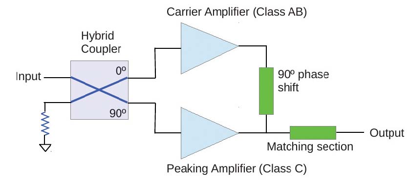
Fig. 1: Simplified Doherty Amplifier Doherty amplifier technology was first developed by William H. Doherty at Bell Labs in 1936. At this time modulation was a lot simpler (AM only). However, as cellular and PCS companies moved from analog FM signals to complex single-carrier and now multicarrier digital modulation, Doherty amplification has seen new use in base station amplifiers as operators seek to reduce power consumption and cooling costs.
The Doherty amplifier (Fig. 1) consists of two amplifiers. One carrier amplifier is biased for Class AB service and amplifies the average power signal with little distortion. It is biased so that above a set RF power, it will go into saturation and its current draw will not increase.
The peaking amplifier is biased to operate in Class C mode, the most efficient mode, but one that creates high amounts of distortion at lower amplitudes. The efficiency comes from operating the carrier amplifier at lower current and using the Class C peaking amplifier, which only draws current on the peaks, to provide the peak power.
The complexity of the Doherty amplifier is in the combining of the two amplifiers. The output of the peaking amplifier is combined with the carrier amplifier so that it “load modulates” the carrier amplifier, enabling a wider voltage swing and avoiding distortion in the crossover area. This requires shifting the RF input of the peaking amplifier 90 degrees and using a 90-degree quarter wave line section on the output of the carrier amplifier to combine it with the peaking amplifier.
The professional video industry's #1 source for news, trends and product and tech information. Sign up below.
I do not have the space to go into Doherty amplifier design here, but even with this very simple description you can see that the setting operating point and gain of the amplifiers, the output impedance of the amplifiers and combining network is not simple. See The Doherty Power Amplifier by Paolo Colantonio, Franco Gianni, Roco Giofrè and Luca Piazzon for a complete explanation including formulas and graphs at http://cdn.intechopen.com/pdfs.Alternatively, look at a software approach using Ansoft Designer at www.ansoft.com/deliveringperformance/poweramp.pdf.
ON THE NAB SHOW FLOOR
The Doherty amplifier modules in the high-efficiency transmitter shown by Screen Services at the NAB Show are able to operate +/– a few TV channels, but greater frequency moves require readjusting the matching/phasing of the amplifiers by a factory technician. Screen Services developed their Doherty amplifier in partnership with Optelex. I was able to see one of the amplifier modules (no photos allowed) and was impressed with the clean design.

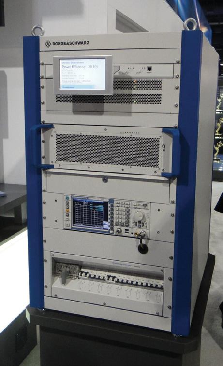
Rohde & Schwarz Doherty Demo Rohde and Schwarz is still in the process of patenting their broadband Doherty amplifier design. Like Screen Services, they had a working UHF TV Doherty amplifier on display, but I could not see the actual amplifier nor pry any secrets from them on how they were able to design a broadband Doherty amplifier that was able to work across the entire UHF TV band without adjustment. It isn’t obvious how they are able to do this without adding a lot of cost and complexity. I’ll have more details when Rohde and Schwarz is able to release them.
Thomson used a different technique for achieving high efficiency in their amplifiers. The concept is deceptively simple. The envelope of the modulated RF input is sampled and used to vary the voltage to the amplifier. At no point is the amplifier using any more power than it needs to deliver the instantaneous RF output level required.
While simple in concept, the implementation is quite complex. First, it is necessary to modulate the voltage to the amplifier at the symbol rate of the modulated signal—several megahertz. Second, the voltage modulation has to be precisely timed to that of the RF modulation at the amplifier. Third, the characteristics of the amplifier change as the voltage to it changes, so precorrection has to compensate for this to avoid creating large amounts of distortion and spurious emissions. Thomson appears to have figured out how to handle these complexities.
If history is any indication, over the next few years we should see improvements in the implementation of Doherty amplifiers and envelope tracking amplifiers and perhaps even a combination of the two technologies. As with improvements in tube technology, the winning high-efficiency solid-state amplifier technology will be the one that offers the best combination of affordability, performance and reliability.
Comments are welcome! E-mail me at dlung@transmitter.com.

Doug Lung is one of America's foremost authorities on broadcast RF technology. As vice president of Broadcast Technology for NBCUniversal Local, H. Douglas Lung leads NBC and Telemundo-owned stations’ RF and transmission affairs, including microwave, radars, satellite uplinks, and FCC technical filings. Beginning his career in 1976 at KSCI in Los Angeles, Lung has nearly 50 years of experience in broadcast television engineering. Beginning in 1985, he led the engineering department for what was to become the Telemundo network and station group, assisting in the design, construction and installation of the company’s broadcast and cable facilities. Other projects include work on the launch of Hawaii’s first UHF TV station, the rollout and testing of the ATSC mobile-handheld standard, and software development related to the incentive auction TV spectrum repack. A longtime columnist for TV Technology, Doug is also a regular contributor to IEEE Broadcast Technology. He is the recipient of the 2023 NAB Television Engineering Award. He also received a Tech Leadership Award from TV Tech publisher Future plc in 2021 and is a member of the IEEE Broadcast Technology Society and the Society of Broadcast Engineers.
