The professional video industry's #1 source for news, trends and product and tech information. Sign up below.
You are now subscribed
Your newsletter sign-up was successful
Most emails I receive from readers relate to over-the-air TV reception in one way or another—viewers and broadcasters alike want to know how to maximize reception. This month I’ll look at how coverage (and reception ability) is calculated and some ways to maximize reception.
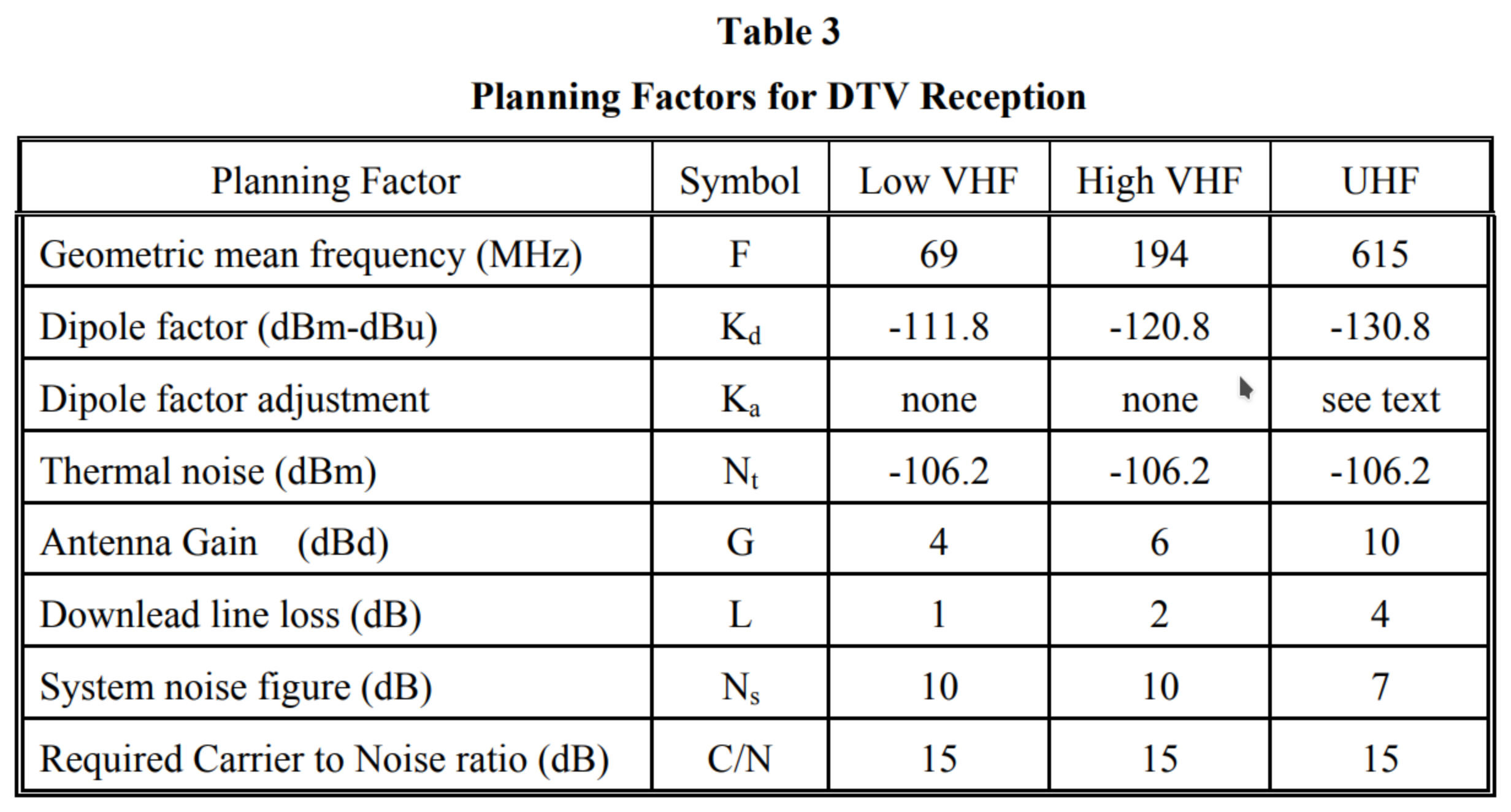
When the FCC defined the coverage for DTV stations, they depended on the planning factors recommended by the ATSC and the former ATTC (Advanced Television Test Center). The planning factors are the basis for a link budget for over-the-air reception, looking at gains, losses and thermal noise.
Table 3 (Fig. 1) from the FCC’s Office of Engineering and Technology Bulletin 69 shows the elements used for determining reception. These planning factors resulted in the FCC setting a required field strength of 28 dBµV/m for low VHF (Channels 2–6) and 36 dBµV/m for high VHF (7–13).

At UHF, the field strength in dBµV/m is determined by the formula:
41–20 log[615/(channel mid-frequency in MHz)]
The planning factors do not include an antenna height, but FCC rules specify that 9.1 meters (30 feet) be used when calculating coverage.
New Sources of Noise
The parameters in the planning factors may have matched consumer TV antenna setups 30 years ago, but they don’t match what viewers expect to be able to use to receive over-the-air TV today. For VHF channels, the contribution of locally generated electrical noise from LED lamps, motors and switching power supplies isn’t included.
Compare the display on a spectrum analyzer with and without the antenna connected and you will see the impact of local noise sources. In my experience this noise can completely wipe out VHF TV reception on indoor antennas unless the signal level from the transmitter is very high. The antenna gain numbers clearly refer to outdoor antennas—indoor antennas typically have very little gain, if any.
The professional video industry's #1 source for news, trends and product and tech information. Sign up below.
On the plus side, with indoor antennas there is little downlead line loss. Finally, the planning factors do not take into account the loss from a reduction in height or the loss getting into a building.
The late Charlie Rhodes provided an excellent description of these losses in his 2009 TV Tech column “Obstacles to DTV Reception.” The signal difference between a rooftop antenna and one in the family room was 31 dB at UHF. Removing the 10 dB antenna gain and adding back in the 4 dB for line loss results in a signal requirement that is 37 dB stronger than that calculated with the planning factors and FCC antenna height.
If we use 41 dBµV/m as the FCC required field strength, adding in the additional losses means a field strength of at least 78 dBµV/m will be required for indoor reception. This is consistent with the “easy indoor” field strength of 80 dBµV/m used on the rabbitears.info website and the 75.5 dBµV/m requirement Meintel, Sgrignoli & Wallace determined based on some limited early indoor measurements of DTV signals.
I use 88 dBµV/m as a reference level for easy indoor reception to allow for non-optimum antenna placement. For details on the calculation of building losses, Google ITU-P2040-2, which was updated in October 2021. Note the differences in loss with different polarization—the graphs clearly show the advantage of elliptical or circular polarization.
Location, Location, Location
What can be done to maximize reception? Antenna location is probably the most critical element, placing it in a location as free as possible of obstacles. This means avoiding trees (particularly pine trees) outside and minimizing the number of walls the signal must pass through with an indoor antenna.
Higher isn’t always better. Ground reflections or reflections from buildings can arrive at the antenna out of phase and cancel out part of the TV band. Lowering the antenna will solve this problem.
Ron Shinno, the engineer who maintains the translators for PBS Hawaii on the island of Hawaii, told me about a case where a viewer had an antenna high in the air, but it was aimed right at a tree, blocking the signal. Lowering the antenna below the level of the leaves on the tree brought the signal back.
I’ve seen cases where reflections from a rooftop or metal structure canceled out a band of frequencies. When I visited with engineers at KXAS-TV in Dallas, they told me about one viewer who had difficulty receiving their OTA signal and a quick check with a spectrum analyzer showed a deep null on KXAS-TV’s channel and adjacent stations.
The viewer wasn’t interested in the adjacent channels so saw this as a station problem, which he solved by lowering his antenna to a foot or two above the roof line. Raising it higher would likely have worked as well but wasn’t an option.
Use a Spectrum Analyzer
Unfortunately, it is almost impossible to optimize indoor antenna location using a TV set alone, especially if there isn’t line of sight to the transmitter site. A field strength meter can help but won’t show multipath—a spectrum analyzer is required. With the tinySA spectrum analyzer (www.tinysa.org/wiki) available for only $60 from R&L Electronics, there is no excuse for not having one.
While the planning factors use a noise threshold of 15 dB for reception, any multipath will reduce this significantly because the adaptive equalizer in the receiver has to add gain (and noise) to fill in the nulls created by the multipath.
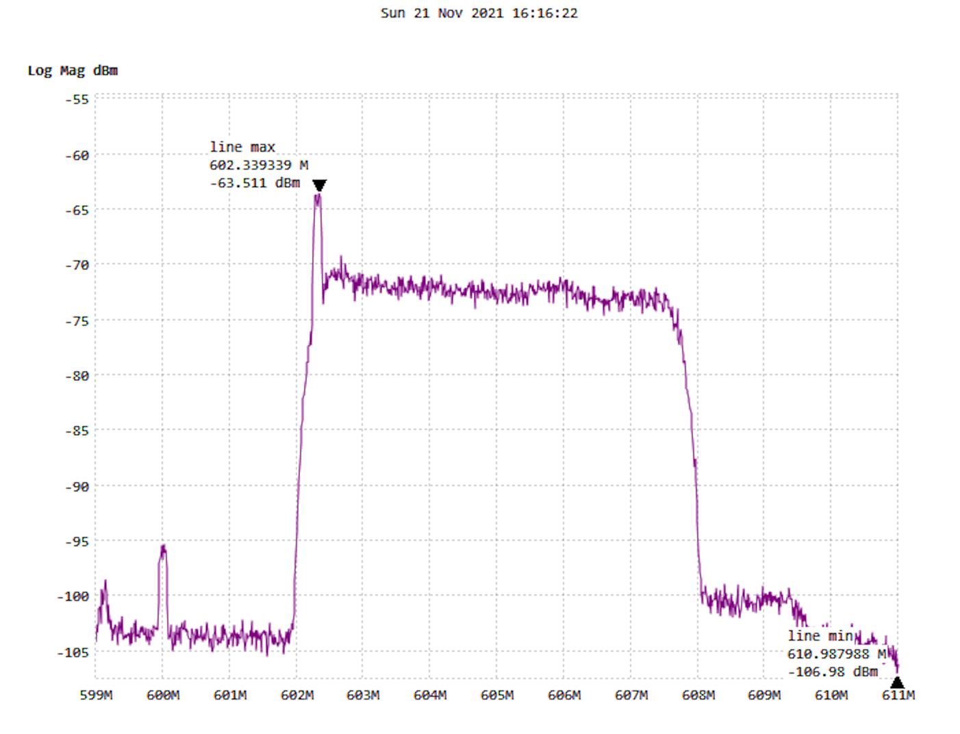
Fig. 2 shows the plot of a well-located Winegard Freevision FV30-BB antenna. If the antenna was picking up multipath, the spectrum would have had ripples in it, with the spacing of the ripple dependent on the distance of the reflection and the amplitude on the strength of the reflection.

When orienting an antenna with a spectrum analyzer, look for the flattest response on the desired channel and across the TV band (the tilt at the upper end of the channel is due to an LTE filter). The antenna referenced in Fig. 2 has a Winegard LNA-200 LNA at the antenna. Winegard claims a noise figure of 1 dB for this LNA, which reduces the system noise to less than the 7 dB specified in the planning factors.
I use the spectrum analyzer to find the best spot and orientation for my indoor antenna in a hotel room when traveling. Where possible I try to get a room facing the transmitter site, which makes things easy, but in some cases that’s not possible.
In one hotel room in Albuquerque, N.M., I found I had to have the antenna in three different places in the room to get different channels, all transmitting from the Sandia Crest Tower Farm. Without the spectrum analyzer, I wouldn’t have been able to find a location with enough signal from some of the stations for the tuner to lock onto.
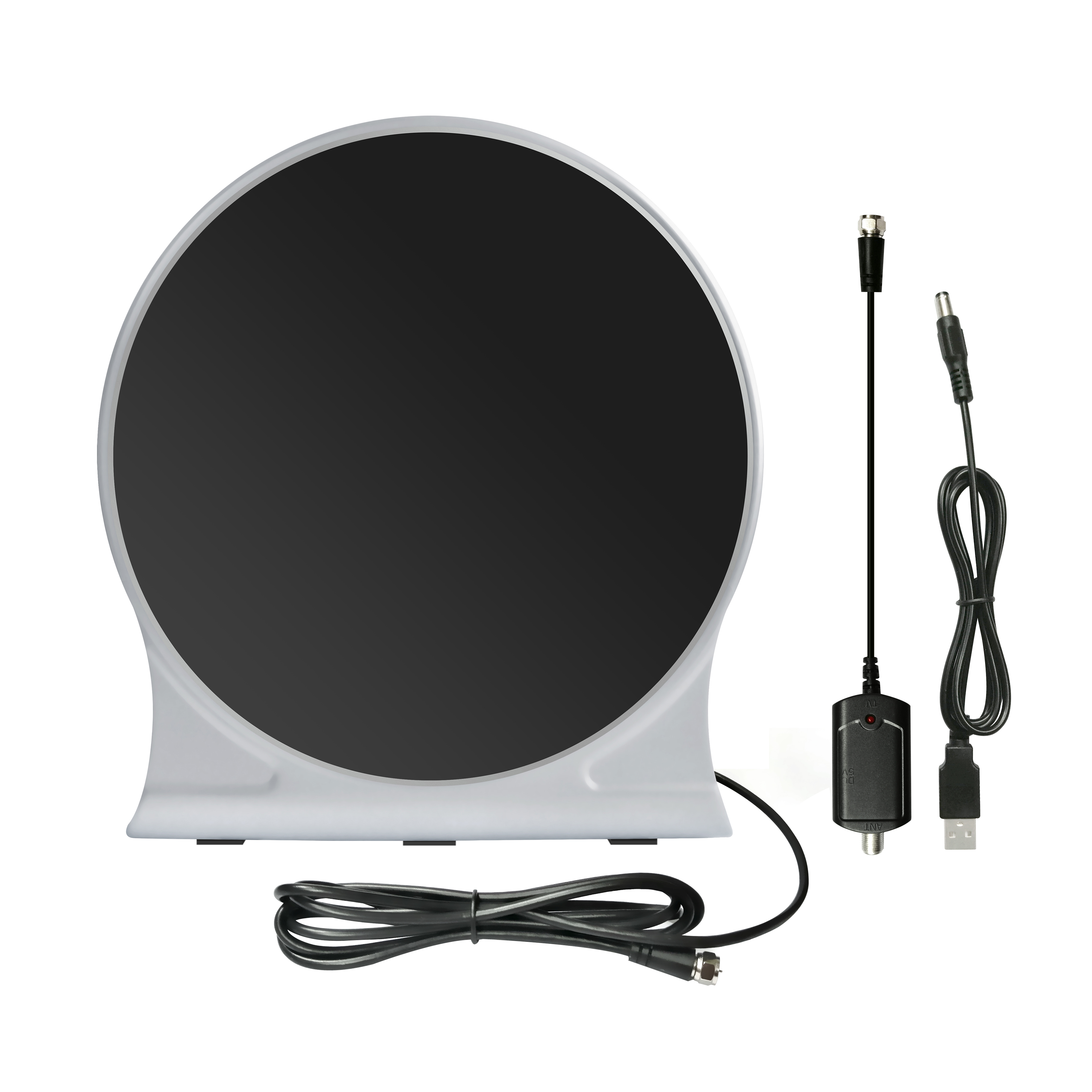
My current choice for a travel antenna is the Walmart onn. Indoor High-Quality Clear HDTV Antenna available in most stores for less than $20.

The planning factors here are for ATSC 1.0. If you are wondering about ATSC 3.0, most ATSC 3.0 stations are operating with parameters that require a noise threshold similar to that for ATSC 1.0, so these examples and required field strengths would apply to ATSC 3.0 as well.
However, in ATSC 3.0, stations can change modulation and coding parameters to work at a much lower noise threshold, expanding coverage. This is particularly
beneficial for LPTV and Class A TV stations that are limited to a maximum effective radiated power of 15 kW. I showed an example of how to do this at the NTA conference in Salt Lake City in May 2021. Look for details in a future column.
As always, I welcome comments and questions. Email me at dlung@transmitter.com. I try to answer all emails promptly, but if I’m busy and the email gets buried, I might miss it. If you don’t get a response within a week or so, email me again.

Doug Lung is one of America's foremost authorities on broadcast RF technology. As vice president of Broadcast Technology for NBCUniversal Local, H. Douglas Lung leads NBC and Telemundo-owned stations’ RF and transmission affairs, including microwave, radars, satellite uplinks, and FCC technical filings. Beginning his career in 1976 at KSCI in Los Angeles, Lung has nearly 50 years of experience in broadcast television engineering. Beginning in 1985, he led the engineering department for what was to become the Telemundo network and station group, assisting in the design, construction and installation of the company’s broadcast and cable facilities. Other projects include work on the launch of Hawaii’s first UHF TV station, the rollout and testing of the ATSC mobile-handheld standard, and software development related to the incentive auction TV spectrum repack. A longtime columnist for TV Technology, Doug is also a regular contributor to IEEE Broadcast Technology. He is the recipient of the 2023 NAB Television Engineering Award. He also received a Tech Leadership Award from TV Tech publisher Future plc in 2021 and is a member of the IEEE Broadcast Technology Society and the Society of Broadcast Engineers.
