Advances in technology have made it cost-effective to use bit-serial distribution of SDTV and HDTV video signals. All of the digital data bits, synchronization information and ancillary data (including several channels of digital audio), can be distributed inside a teleproduction plant through a single coaxial cable.
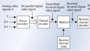
Bit-serial signal distribution model
The source encoder consists of three A/D converters (one for each of the Y, B-Y, and R-Y analog video signals) followed by a time-division data multiplexer. The output of the multiplexer is a sequence of CB, Y, and CR parallel 10-bit words. The channel encoder transforms the bit-parallel digital signal into a bit-serial digital signal suitable for transmission through the chosen medium (e.g., coaxial cable). The received signal is corrupted to some degree by thermal noise. In a studio environment, it is the receiver input stage that contributes most of this noise. The receiver channel decoder deserializes the received bit-serial signal and recovers the bit-parallel digital video signal. Poor signal-to-thermal-noise ratio at the receiver input may affect its ability to reconstruct the original signal, resulting in erroneous or missing bits. The output of the receiver channel decoder is the original sequence of CB, Y, CR. The signal decoder consists of a conventional demultiplexer followed by a set of three D/A converters, recovering the original Y, B-Y and R-Y analog component video signals.
The bit-serial data rate is given by:
Bit-serial rate (Mbits/s) = Parallel-word rate (Mwords/s) × Number of bits per word
The SDTV 4:2:2 bit-serial rate is given by:
Bit-serial rate = 27 Mwords/s × 10 bits/word = 270 Mbits/s
The normalized HDTV bit-serial rate, based on 60 fps, is given by:
Bit-serial rate = 148.5 Mwords/s × 10 bits/word = 1.485 Gbits/s
The 59.94 fps data rate is equal to 1.485 Gbits/s/1.001
Claude Shannon's guidelines
According to Shannon, a noisy communication channel has a specific capacity measured in bits per second. The channel capacity is given by the well-known formula:
C(bits/s) = B log2 [1+(S/N)], where
B = The channel bandwidth (Hz),
S = The received signal power (W), and
N = The accompanying noise power (W)
In a studio environment, the first amplifying element of the receiver contributes most of the thermal noise. Thermal noise from other sources, and other types of noise, are present but negligible. The signal-to-noise ratio (SNR) at the input of the receiver depends on the attenuation of the interconnecting coaxial cable and the equivalent input noise of the receiver. This puts a limit on the length and associated signal attenuation of the coaxial cable connecting the transmitter and the receiver.
At a given room temperature, the thermal noise power is proportional to the bandwidth. This is described in the formula N = kTB, where k is Boltzmann's constant, T is the noise temperature in degrees Kelvin, and B is the bandwidth in Hz. The channel capacity can then be expressed as:
C(bits/s) = B log2 [1 + (S/kTB)]
Shannon's theorem states that it is theoretically possible to transmit information with a low probability of error through a channel having a specific capacity provided that the transmission rate is lower than the channel capacity. Shannon does not specify the means of obtaining an error-free transmission over a specific transmission channel, but simply states that there are means of achieving it. Each method results in a specific channel coding.
The channel coding describes the manner in which the 1's and the 0's of the data stream are represented on the transmission path. There are many channel-coding standards, and they all aim at optimizing some aspect of the bit-serial digital signal. The SDTV and HDTV bit-serial channel coding use the Non Return to Zero Invert (NRZI) scrambled method. The result is an increase in the number of 0-to-1 transitions and the randomization of their occurrence to aid in the recovery of the clock in the receiver. A detailed description of this method is beyond the scope of this article.
Figure 1 shows the spectrum of the 4:2:2 SDTV and HDTV NRZI scrambled bit-serial digital signals. The spectrum is typical of a suppressed-carrier pulse-amplitude modulation (PAM) with nulls at the sampling frequency and its multiples. The distribution of this type of signal requires very wide bandwidths — on the order of half the clock frequency. In a studio environment, this requirement can be best accommodated by adequate hardware technology.
Figure 1. Bit-serial digital spectrum of SDTV and HDTV formats.
Bit-serial distribution standards
The SMPTE Standard 259M specifies the characteristics of the bit-serial interface for 525/60 and 625/50 digital equipment operating with either 4:2:2 component digital signals or 4fSC composite digital signals. The standard can be applied in television studios where the length of coaxial cables used in the studio does not exceed that specified by the receiver equipment manufacturer. In such applications, the signal loss at the receiver input is typically 30dB either at the clock frequency or half the clock frequency. The Belden 8281 coaxial cable, for example, has a loss of 30dB at 135MHz. Current receiver technology is capable of automatically equalizing losses introduced by up to 300 meters of this coaxial cable. Using a safety margin of 100 meters reduces the useful length of this cable to about 200 meters.
The SMPTE Standard 292M specifies the characteristics of the bit-serial interface common to several HDTV source formats operating at 1.485 Gbits/s and 1.485/1.001 Gbits/s. This standard deals with 1125-line, 1250-line (European HDTV) and 750-line scanning formats. Current receiver technology is capable of automatically equalizing losses introduced by up to 100 meters of Belden 1694A coaxial cable. Using a safety margin of 15 meters, the equalizing capability is of the order of 85 meters. For longer distances, fiber-optic distribution systems must be used instead of coaxial cables.
Figure 2. Eye diagram measurement dimensions.
Figure 3 shows the outline of the NRZI scrambled bit-serial digital signal. This signal is commonly called the “eye diagram.” The name results from the appearance on a storage oscilloscope of sections of digital symbol patterns superimposed on one another. For an infinite-bandwidth system, the transitions from 0 to 1 are instantaneous and, consequently, the “eye” is square. But practical systems have a finite bandpass, resulting in transitions with a slower rise time and decay time, which show up on storage oscilloscopes as the familiar eye shape. Bit-serial signals are specified in terms of eye amplitude, rise time, decay time, overshoot and jitter.
Table 1. Transmitter characteristics of bit-serial interfaces.
Table 1 summarizes the transmitter (bit-serial signal source) characteristics. Of particular importance are the tolerances of the eye-diagram parameters as well as the impedance matching of the signal source to the coaxial cable, specified in terms of return loss. Table 2 lists the jitter specifications and the frequency domain to which they apply.
Table 2. Jitter specifications of bit-serial interfaces.
Michael Robin, former engineer with the Canadian Broadcasting Corporation's engineering headquarters, is an independent broadcast consultant located in Montreal, Canada. He is co-author of Digital Television Fundamentals, published by McGraw-Hill.
Send questions and comments to: michael_robin@intertec.com
