Testing SFNs for ATSC Reception
The professional video industry's #1 source for news, trends and product and tech information. Sign up below.
You are now subscribed
Your newsletter sign-up was successful

In my last column (“Will SFN’s Work in N. America?” Digital TV, June 23), the best ATSC and DVB-T (European DTV standard) DTV receivers were compared with respect to static echo rejection and dynamic rejection of one echo.
This comparison showed very substantial differences between the best DVB-T receiver and the best ATSC receiver as tested by the Mackenzie Presbyterian University in Brazil in 2005. The DVB-T system uses COFDM modulation, which was designed to enable single frequency networks (SFN) of multiple transmitters simultaneously serving the same community from different sites with the same program.
This should be of interest to North American broadcasters, as it could be that the FCC will propose to change the TV transmitter topology from what we now have: one transmitter per station, with a tall tower radiating enough power to cover the entire community. Could an SFN support our ATSC standard, or would we have to change our DTV standard to embrace COFDM and thereby obsolete millions of receivers? That is the question.
There is also a question of whether the adaptive channel equalizer unique to our ATSC system can reject the additional echoes which reach receivers.
SFN SYNTHESIZER
The simplest SFN would have three transmitter sites within the community synchronously transmitting the same program on the same channel. The strongest of these three signals would be “captured” by the receiver and the signals from the other two transmitters would be received as echoes and those would be rejected by the adaptive channel equalizer, which is an extremely smart filter.
In my opinion, the 2005 test results from Brazil were not promising for the adoption of SFNs by the FCC, as it seeks to transfer 120 MHz of television broadcast spectrum for wireless broadband.
Some of my colleagues and I designed and built an SFN synthesizer. We planned to use this laboratory instrument to test 16 different makes/models of NTIA-approved DTV downconverters, which represented the chipsets available for DTV receiver manufacturers circa 2008. The NTIA said that about 33 million of these downconverters were purchased by the public using $40 coupons.
That program is now complete.
About 100 different models of downconverters were tested at the FCC laboratory and approved for the NTIA coupon program. These units are equipped with one of the 13 chipsets available for such applications—that narrows down the scope of testing on our simulator. With facilities for 16 downconverters, all 13 chipsets could be tested at once. But there was a snag: Which of these more than 100 models have which chip sets?
We learned that the downconverters we obtained had nine of the 13 possible chipsets. We also found out what downconverter makes and models had chipsets that were not already represented in our inventory of downconverters. We were able to augment our inventory of downconverters with units that we believe were built with most of the chipsets not already represented.
So what should be measured with our simulator?
Testing for echo rejection is usually done at a specified desired DTV signal level. The best way to ascertain the effect of echoes within the range over which the adaptive channel equalizer can reject echoes is to increase the noise in the desired signal channel, thus lowering the signal-to-noise ratio (SNR). If the SNR is very high, the noise enhancement due to echoes adds noise, but this does not lower the SNR to near the ATSC threshold of 15.2 dB.
We started testing with a desired signal power of –50 dBm, the level used in the 2005 tests cited above.
We could set the maximum power of the strongest signal to any desired level, and we could also set each of as many as four echoes to a lower power—i.e. 1 or 2 dB lower than the strongest signal. I call it the D/E ratio, and we elected to use 2 dB.
We could delay each of three of our signals by as much as 108 microseconds. For example, we could delay one signal up to 54 microseconds after the first signal, and then delay another up to 54 microseconds beyond the less-delayed signal.
If the first signal detected was the strongest, it was recognized as the signal to demodulate. If the second signal happened to be stronger, then the first would appear as a “leading echo,” while the third and last signal was seen as a lagging echo. By selectively changing the attenuation of the three signals, we could simulate two trailing echoes after the strongest signal, or two leading echoes before the strongest signal. The fourth signal could be either “the signal,” or appear as another echo.
Our master attenuator reduced the ensemble of desired signal (D) plus echoes. We could set our strongest signal at D = –88 dBm, with our echoes at –90 dBm.
Next we observed the screens of our analog TV monitors. They were all “dead,” and there was no audio indicated on our set of 16 digital volume unit (VU) indicators. We then reduced the signal attenuation with the master attenuator, and as we did this, screens began to display pictures and the VU meters showed that audio was being decoded. We noted the master attenuator settings at which each receiver become stable.
NEAR THE EDGE
These tests demonstrated how existing NTIA-approved DTV downconverters might behave in a SFN environment.
Suppose that we found for a D/E of 2dB, that the units all required a minimum usable signal power of –73 dBm. It then became obvious that instead of being able to receive DTV signals at D = –84 dBm, there was a SFN penalty of 11 dB, where the strongest signal was –77 dBm, 11 dB above the noise-limited threshold.
This means that reception near the edge of coverage is impossible. If we use the “rule of thumb” that field strength decreases 1 dB per km. of distance from the transmitter, the DTV perimeter has shrunk by 11 km. (6.5 miles).

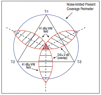
Fig. 1: A sample SFN of three transmitters However, a moment’s thought will show that where SFN echoes cause DTV reception to fail is not only near the edge of noise-limited coverage, but also in the shaded areas between transmitters as shown in Fig. 1. DTV reception may be unreliable within the shaded areas between transmitters where D/E is too close to zero dB for ATSC receivers to operate reliably.
This assumes that each transmitter has the same ERP and that height above average terrain for all transmitters is the same, and that all stations use omnidirectional antennas. A further bit of thinking suggests that if the receiving antenna is a directional rooftop antenna, it will be aimed towards one transmitter and away from the nearest of the two others. If the front-to-back ratio of such a directional antenna is 14 dB, then the strongest echo may be reduced by 16 dB relative to the strongest available signal, which would allow reception.
On the other hand, reception would probably be impossible with indoor antennas, unless one transmitting tower can be seen through a window in the TV room.
Our interest is in finding out how well the 33 million downconverters will work if the FCC were to mandate changes in TV transmitter topology to that of single frequency networks.
Echoes are but one of the problems that may plague SFN implementation in this country. I expect echoes to abound when short towers are used for DTV as is envisioned for SFN implementation.
I also expect that with any SFN scheme that allows the FCC to repack the spectrum with cochannel allotments at significantly reduced spacing, the average field strength within the noise-limited contour will decrease. So you can say goodbye to indoor antennas and say hello to rooftop, directional antennas, of which many may need to be equipped with low-noise amplifiers.
Finally, I also expect FM interference to increase, as I do not expect the FCC to change its rules for FM broadcasting. So, also say hello to FM band 75-ohm traps that will be needed to restore reception of VHF DTV signals.
Charles Rhodes is a consultant in the field of television broadcast technologies and planning. He can be reached via e-mail atcwr@bootit.com.
The professional video industry's #1 source for news, trends and product and tech information. Sign up below.
