Moving Into an Interference-Limited Environment in 2015
The professional video industry's #1 source for news, trends and product and tech information. Sign up below.
You are now subscribed
Your newsletter sign-up was successful
Charles W. Rhodes
This column has used the term “D/U ratio” (desired/ undesired) in describing how the FCC might repack the UHF TV spectrum. In fact, the FCC must use this parameter because FCC/OET Bulletin No. 69 in dealing with interference gives the interference protection in terms of D/U ratios (see the bulletin’s Table 5A).
Except for co-channel interference, (CCI) all D/U ratios are negative numbers expressed in decibels. This gets awkward when a large negative number such as –60 dB means that a receiver is extremely robust while less robust receivers have a D/U such as –30 dB. I think that the use of D/U to characterize the robustness of receivers is a new application.
The D/U ratio of a receiver is the largest difference between desired and undesired signal powers at the RF input of that receiver at which it is able to operate. This is the way I think of it because this makes clear that D/U is the limiting parameter for reception of DTV signals. The critical D/U ratio is constant over a wide range of U signal received power.
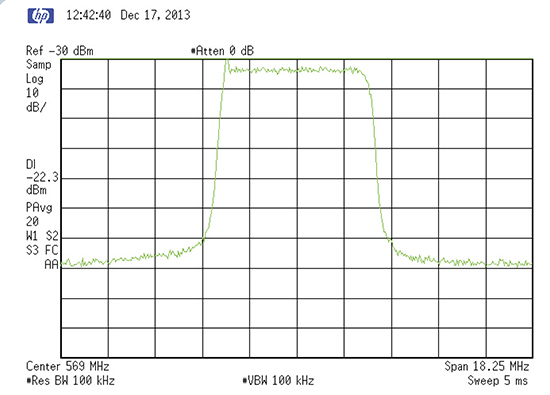
Fig. 1: ATSC signal spectrum at the input to a transmitter Historically, we lived in a noise-limited world just as Marconi did when he transmitted the letter S across the ocean circa 1901. His was the only station on-the-air. Many engineers believe the increased number of stations on the remaining UHF channels will result in increased DTV-DTV interference when repacking is fully implemented.
The FCC recognizes co-channel interference and adjacent channel interference (ACI). My concern is over the extensive use of what we old-timers called taboo UHF channel interference (TCI). The FCC does not recognize TCI between ATSC signals. I believe we will soon move into an interference-limited world, like it or not.
ADJACENT CHANNEL INTERFERENCE
ACI is caused by third-order nonlinear distortion products generated in the high-power amplifiers of DTV transmitters. These third-order distortion products are largely attenuated by the RF mask filter at the transmitter so that only a small fraction are radiated. But that small fraction is what causes ACI.
The professional video industry's #1 source for news, trends and product and tech information. Sign up below.
Fig. 1 shows an ATSC signal in a UHF channel at the input of the power amplifiers of a TV transmitter. This signal spectrum is confined to the channel limits 6.0 MHz apart.
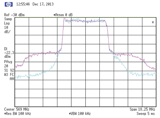
Fig. 2: ATSC signal spectrum at the output of the transmitter (magenta trace) and after the RF mask filter (blue trace)
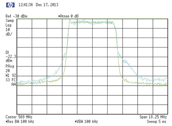
Fig. 3: ATSC signal spectrum at the input to the transmitter (green trace) and after the RF mask (blue trace) Fig. 2 shows the spectrum of the ATSC signal at the output of the final amplifier. This spectrum is spread out over three contiguous channels. The side channels do not carry any useful information. What is there is sideband splatter (noise). This noise is the cause of ACI. If we have two stations allocated adjacent channels, half of the sideband splatter (noise) of each transmitter falls in the other station’s channel.
This was well-known to the FCC, so they set a limit on the radiated noise power of each ATSC signal. They did this by defining an RF mask, which every full-power ATSC signal must comply with.
The “IEEE Recommended Practice for Measurement of the 8-VSB Digital Television Transmission Mask Compliance for the USA” was largely written by my colleague Linley Gumm. It can be obtained from the IEEE where it is known as IEEE Std. 1631-2008.
The effect of the RF mask is shown in Fig. 3. The noise power under the mask in each adjacent channel is 46.5 dB below the power of the radiated signal in the allocated channel. This is about 22 watts average power, enough to cause a lot of interference to other stations on adjacent channels.
Recently Gumm and I conducted a test of seven modern DTV receivers for their robustness to ACI. Both our D signal on channel N and the U signal on channel N+1 were generated by Rohde-Schwarz DTV signal generators.
The U signal was deliberately distorted by carefully overloading an amplifier to simulate the transmitter’s output signal. As Fig. 1 shows, the spectrum of the D ATSC signal is strictly confined to the channel N. As Fig. 2 shows, the spectrum of the U signal on channel N+1 spills from the U channel into both adjacent channels. We filtered the distorted U signal (with sideband splatter) with a RF mask filter, courtesy of Larcan. The filtered signal spectrum (blue trace) is shown in Fig. 3 along with the transmitter input signal (green trace).
We measured the threshold D signal power at which our bank of seven modern ATSC receivers could acquire the D signal and display artifact-free pictures. Table 1 reports our results with the simulated broadcast signal shown in Fig. 3 (blue trace). Table 1 also shows our results when the U signal was taken directly from the signal generator and was therefore free of sideband splatter (noise) in the D channel.
Sideband Splatter in D Channel 49.5 dB Below U Power in Adjacent Channel

Note: Sideband Splatter 49.5 dB below U power is 3 dB below FCC Limit (U -46.5 dB). This is typical of ATSC Transmitters
Table 1: Laboratory test results for ACI with seven modern ATSC receivers Without sideband splatter, the D/U ratio was significantly changed for the better (about 6 dB) compared to the D/U when we simulated a real-world transmitter. Thus, we have demonstrated that ACI is due to the transmitter-generated nonlinear distortion products (sideband splatter). Those differences are given at the bottom of Table 1. This difference, typically 6 dB, means that the interference in the D channel was four times greater with sideband splatter 49.5 dB lower than the U power, than if the U signal were to be radiated free of sideband splatter.
The FCC limit on sideband splatter is 46.5 dB below the U power so our results are not “worst case,” but we believe they are representative of what transmitters do in practice.
Next month, more test results with these modern ATSC receivers will be revealed and analyzed. Stay tuned,
Charles Rhodes is a consultant in the field of television broadcast technologies and planning. He can be reached via e-mail atcwr@bootit.com.
