Lining Up Transmission Failures
JOHNSTON, IOWA: On Aug. 19, 2005, Iowa Public Television turned on KHIN-DT in Red Oak, Iowa. This station operates on digital Channel 35 with a companion analog station on analog 36. Over a few years, IPTV has replaced the original RCA Channel 36 slot antenna with a new Dielectric two-channel slot antenna.
Last summer we completed construction of a new digital transmitter building adjacent to the existing analog transmitter building. In this building we have installed our "new" Harris three-cabinet Diamond transmitter with its associated test and measurement equipment rack and three port Gysel combiner. Also installed in the building is the new 2-channel transmitter combiner that combines the DTV and NTSC transmitter outputs into a single transmission line run.
HEATING UP

Fig. 1 The DTV transmitter only recently went to full power due to some missing components that had to be fabricated, so although it's been operational since August, full power operation began Oct. 21. On Nov. 20, the DTV transmitter went off the air and engineers at the site discovered that the problem was in the transmission line between the three-port Gysel combiner and the N-1 channel combiner.
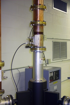
Fig. 1 shows the transmission line stack coming out of the Gysel combiner that is made up of the low-pass filter, a line section with a monitoring probe and then a cut transmission line piece to the horizontal run over to the N-1 combiner.
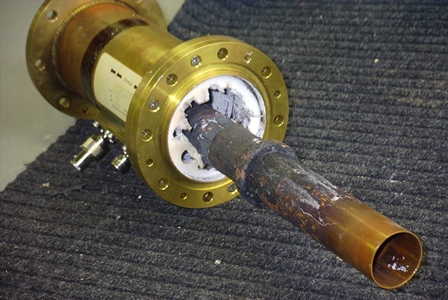
Fig. 2 shows the probe section removed from the output stack. The additional section of inner conductor is the low-pass filter inner conductor. Due to the extreme heating that had occurred, the inner conductor sections were fused and could not be separated. The failure was the result of excessive heating at or near the flange. Given that this particular DTV transmitter is a three-cabinet unit and that after the Gysel combiner, we are generating approximately 21 kW average power, our primary concern about this failure was whether it was due to some reflection or moding in the transmission line.
I have seen similar failures in UHF operations when the 6 1/8-inch or larger transmission line is used and an elbow is inserted in the circuit prior to the low-pass filter. In the 1960s, Bill Smith at Harris wrote a paper on some lab work he did to explain some odd behaviors at various UHF installations. It appears that when a transmission line diameter reached approximately six inches, a UHF signal could generate modes in an elbow, unless the signal was first routed through a low-pass filter.
These modes would then travel with the coax acting as a waveguide. Since a coax low-pass filter works only on a signal traveling on the center conductor, the low-pass filter has no predictable effect on the modes. These high-order modes are typically beyond the frequency range of the monitoring and measuring equipment used at a UHF site and therefore can go completely unnoticed.

Fig. 2 At least that is until they cause a failure. Unfortunately, that does not appear to be a possibility at this site since all of the transmission line feeds coming from the three cabinets are smaller than 6 1/8 inches and the low-pass filter is mounted directly on the output of the Gysel.
ISOLATING THE FEEDS
Another possibility would be that the probe section actually caused the problem. In theory, the actual probe element could have been too close to the inner conductor and set up a resonate circuit, which caused the heating. I have a hard time visualizing how that is possible. Given the obvious indication of how intense the heat was in this area and the relatively small amount of metal that makes up a transmission line probe, I would have expected that the heat would have destroyed the probe element long before it caused the level of damage that is obvious in the pictures.
The third possibility is that the problem is in the Gysel itself. In my efforts to understand what happened, I did some research on the Gysel combiner and quite frankly, the circuit is so simple I would be surprised if the problem is in that device. As I understand it, the basic Gysel design at this site takes the outputs of the three transmitter cabinets in phase and feeds them on equal length transmission lines to the combiner.

Fig. 3 Each of the transmission line inputs splits the signal. Using one-quarter wave line sections, the inputs are fed to a common point for the full-power output. The other one-quarter wave sections feed the reject loads. The loads are also all tied together using one-quarter wave sections to a common point. By doing this, the combiner uses the phase relationships in the signal paths to cancel out any signal in the loads. This provides isolation between the feeds as well as predictable performance when an amplifier is offline or disconnected.
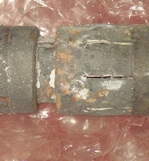
We sent the Gysel and damaged line sections to ERI for repair and diagnosis. Their post-mortem was not really conclusive. The most likely cause is shown in Fig. 3. This close-up that ERI supplied shows a suspicious bulge where the Gysel output mated to the directional coupler section. Since the coupler was added after installation, we cannot determine if the connector was damaged during the install or if it was a result of the size differential between the Dielectric and ERI supplied line sections. Evidently, there is some small difference in the diameter of the inner conductor between these two manufacturers.
REPAIRING THE DAMAGE
In any case, our best course of action is to repair the damaged components, reinstall the hardware and monitor the line section for any further problems.
If you're interested in learning more about the moding work done by Bill Smith, I believe that Harris can still supply his white paper, although I rather enjoyed having Bill explain it to me while working on a UHF transmitter project on Sandia Crest in New Mexico. If you're interested in getting more information on the Gysel combiner and your German is up to it, http://home.zhwin.ch/~gys/ is the home page of Ulrich Gysel. There are also several of his papers available from the IEEE Web site at www.ieee.org.
Bill Hayes is the director of engineering for Iowa Public Television.
The professional video industry's #1 source for news, trends and product and tech information. Sign up below.
