Designing Production Flexibility and Efficiency Using a Combined AV Processing Approach
The professional video industry's #1 source for news, trends and product and tech information. Sign up below.
You are now subscribed
Your newsletter sign-up was successful
As the need for specific audio and video format conversions has increased, so too has the demand for engineering flexibility and processing speed during studio and remote productions. In many instances the studio or truck will often have a collection of video frame syncs and converters at the ready. While these devices are historically thought of as video processors, they can also usually convert audio as well. One such device is the AJA FS2 Frame Sync and Video Processor.

At Georgia Public Broadcasting, under the leadership of Chief Technical Officer Adam Woodlief, we recently redesigned our control rooms to focus on enhancing performance and flexibility to meet growing production demands (Fig. 1). As part of the process, we discovered a need to originate AES-based audio from embedded HD/SDI video sources.
In addition to the AES audio needs, color correction capability was also specified for two video channels of the production control room graphics system. With these specific needs, and in large part due to a surplus availability, the AJA FS2 unit was implemented for both audio and video processing without the need for additional hardware.
In Fig. 2, a block diagram from the FS2 manual shows two independent processors for video and two processors for audio, which can both push AES or analog audio. When using the AES option, the Audio 1 processor is set up to pass either analog or AES. Unlike the video processors, the audio processors can pass converted audio from more than one source at a time—this capability is often overlooked when the focus is strictly on video.
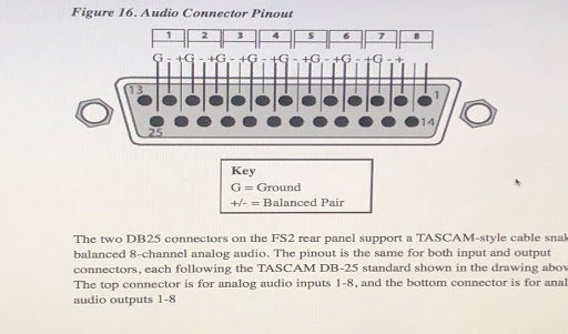
On the back panel of the FS2, a DB-25 AES output connector will allow eight (2) channel AES output groupings of either or both SDI input channel combinations.
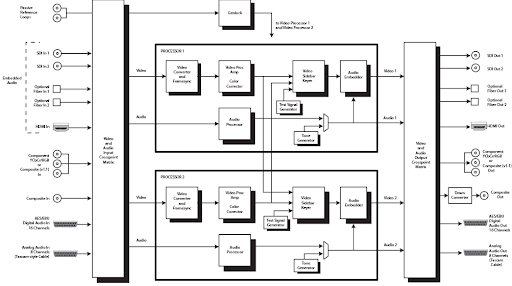
It is important to note that there are two separate processor blocks in the block diagram and that the processors are not fixed to a specific input channel. The Audio Input Crosspoint matrix allows audio associated with either SDI input channel to be mapped to the AES/EBU output port on the rear DB-25 connector by way of the Audio Output Crosspoint Matrix.
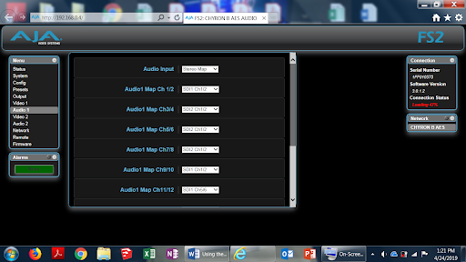
For our conversions, we used the Audio 1 processor to deliver AES audio associated with each of the two graphics video channels. A key point when configuring is to select the Audio Map parameters and map both the SDI 1 and SDI 2 input embedded audio sources via the “Audio 1” processor (Fig. 3). These assignments can be made by accessing the Audio 1 processor either by front panel access or the browser-based GUI.
The professional video industry's #1 source for news, trends and product and tech information. Sign up below.

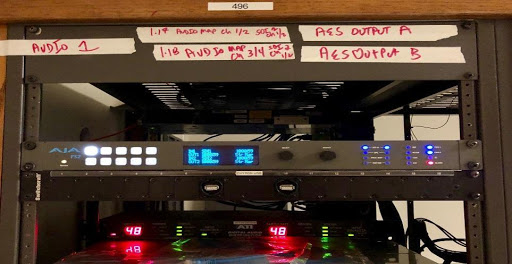
In the “Audio 1” menu settings, go to Menu Sub section 1.17 on the front panel, Audio1 Map Ch 1/2, and select SDI1 Ch 1/2.
Next, go to Menu Sub section 1.18 Audio1 Map 3/4 and select SDI2 Ch 1/2 (Fig. 4).

Once these changes are made using either access method, there will be two independent SDI-based AES channel subgroups; Ch 1/2 from the SDI1 Video source, and Ch1/2 from the SDI2 video source. These four collective AES channels are output to the DB-25 (Fig. 5.) on the corresponding Ch 1/2 and Ch 3/4 (three-pin) groupings.
Using the FS2 in our facility allowed us to configure our AES audio channels to serve as two independent stereo audio channels for both graphics video output channels, with the ultimate result being the delivery of video- and audio-processed signals from one box. The AES signals were then distributed to a 1RU Wohler AES audio monitor at the graphics operator station in the control room, and to a Studer Vista 9 series audio console via a digital I/O unit. The color corrected SDI signals from the graphics system were further distributed for use elsewhere in the facility via HD routing. Initial setup of the FS2 unit via front panel access is shown below in Fig. 7.
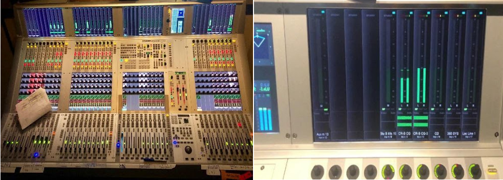
The resulting output on the Studer audio console corresponds to two (2-channel) AES groups. Fig. 8 shows both a 1 kHz audio signal originating from a test unit as well as a second audio signal from an independent SDI source.
The desire to streamline engineering often drives integration of signal processing into a single unit, resulting in fewer components and lower costs. Organizations like Georgia Public Broadcasting can realize enhanced performance and flexibility while achieving critical cost savings using this approach.
Daniel Hall is a broadcast engineer with Georgia Public Broadcasting.
