Lately I’ve seen a number of discussions about adding a frequency offset to an ATSC 1 signal to reduce interference. The issue came to light when it was discovered that at least one major manufacturer’s transmitters do not meet the manufacturer’s FCC emission mask test when the recommended co-channel ATSC offset is added.
This month I’ll look at what ATSC has to say about frequency offsets and how they work. The ATSC 3.0 standard also includes options for not only frequency offsets but bandwidth reduction as well.
Finally, I’ll report on my recent testing of the Hauppauge WinTV quadHD USB ATSC tuner. It uses a different tuner/demodulator chip than I’ve seen used with any other ATSC USB tuner.
REDUCING CO-CHANNEL INTERFERENCE
I’m often asked what the tolerance is for the ATSC 1 pilot frequency. Many assume it is the same ±1 kHz tolerance that was used for analog TV, not including the 10 kHz offset the FCC specified in some cases.
The correct answer is that the FCC does not specify a frequency tolerance for digital TV (ATSC 1 or 3.0) transmissions except in relation to lower adjacent analog TV stations. Excluding that case, the only requirement is that the emissions from the transmitter comply with the mask requirements in Section 73.622(h) (see sidebar).
Back in 1998, I wrote about frequency offsets for ATSC 1 in my column; most related to analog stations. The FCC rules mandate an ATSC station must have its pilot carrier 5.082138 MHz above that of the lower adjacent NTSC station’s visual carrier. This is 22.697 kHz above the normal 309.440559 kHz offset from the channel edge, assuming the DTV signal is centered in the 6 MHz TV channel. The tolerance is ±3 Hz. (This offset won’t be relevant after July 13, 2021, when all LPTV stations must cease analog broadcasting.)
The professional video industry's #1 source for news, trends and product and tech information. Sign up below.
One of the offsets remains relevant—between two ATSC 1 stations operating on the same channel. This offset is defined in ATSC Recommended Practice A/64B, (section 5.1.6.1). It states:
“In the DTV co-channel interference condition, it has been found that a DTV pilot frequency offset that is an odd multiple of half the DTV segment rate provides improved interference rejection. There are several choices that meet this requirement. An offset of 1.5 times the segment frequency (i.e., 19,403 Hz) appears to provide the best performance. The frequency tolerance of the DTV transmitters should be ±10 Hz.”
This ensures the frame and segment syncs of the two signals don’t line up. With this offset, they will alternate and be averaged out in the receiver.
Will a transmitter meet the requirements of FCC 73.622(h) with a 19,403 Hz offset? It seems it should, since when analog stations were on the air, some DTV transmitters had to meet this requirement with an even greater offset, 22,697 Hz, to comply with FCC 73.622(g). A number of devices, including transmitter exciters and external devices like the Avateq receivers display the 500 kHz shoulder levels in dB.
However, I suspect these are referenced to the pilot carrier frequency, which, if offset, may not represent the 6 MHz channel spectrum and could show compliance when the transmitter’s emissions are actually outside that allowed by 73.622(h), which only references channel edges.
I welcome comments from transmitter manufacturers on this question and also would be interested in any studies that show how much a precision offset reduces co-channel interference. With the repack complete, we now have stations on the same channel closer together, particularly LPTV stations, so it is important to see if offsets are worth employing to reduce interference.
ATSC 3.0 BANDWIDTH, FREQUENCY OFFSET OPTIONS
The ATSC references frequency offsets to avoid interference between ATSC 3.0 stations. According to the A/324 standard, section 10.3.3.1:
“Pilot pattern overlap always occurs when neighboring co-channel stations use the same FFT sizes, guard intervals, and pilot patterns. Even when neighboring co-channel stations use some different Physical Layer parameters (FFT sizes, guard intervals, or pilot patterns), there may be partial pilot overlap, depending on the choices of pilot patterns. Such pilot pattern overlap (both full and partial overlap) causes the sorts of channel estimation errors described above, which result in reception failure or performance degradation. To avoid overlapping pilot patterns, offset of Transmitter Center Frequencies shall be used.”
The offset is zero or ± the 8K carrier spacing, which is 843.75 Hz. This is more important than the ATSC 1 co-channel offset because the ATSC 3.0 configurations can allow reception at low signal-to-noise ratios, which makes interference more likely where signals overlap. Obviously this will require coordination between stations, possibly over a wide area.
If required by the ATSC 3.0 transmitter and filter, the overall occupied bandwidth can be reduced from 5.832844 MHz to as little as 5.508844 MHz (see the ATSC A/327 Physical Layer Recommended Practice section 4.2.2 for details).
Bandwidth reduction is unlikely to be needed to handle a less than 1 kHz offset but may be needed to work with existing filters or in adjacent channel interference situations when combined with an offset.
HAUPPAUGE WINTV QUADHD USB TUNER
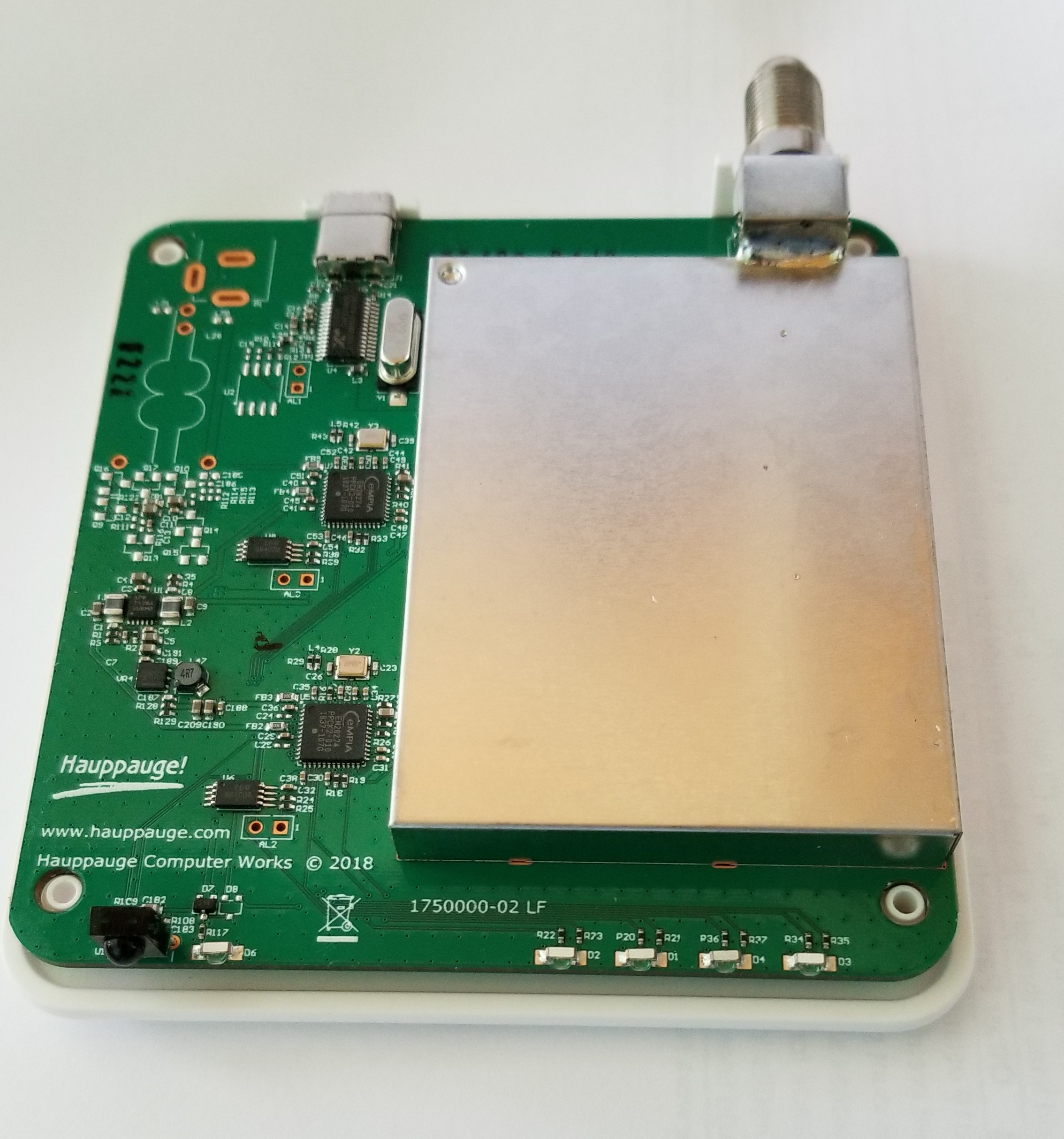
After seeing support for the Hauppauge WinTV quadHD ATSC tuner was in Linux, I ordered one so I could put it to the test. Fig. 1 shows what's inside. I haven’t had a chance to test it on the road yet so I didn’t want to risk removing the RF shield.
All that’s visible is the EM28274 Empia controller and the Maxlinear/Exar XR22404 4 port USB hub, which is connected to a USB-C connector. While Hauppauge says USB-C is required to supply the power and speed for the quad tuners, the supplied cable has a USB 3 type A connector on one end and worked fine on my laptop’s USB 3.1 port in limited testing.
Unlike most ATSC USB ATSC receivers that have a separate tuner (such as the Si2157) and a separate demodulator (like the LGDT3306), the MxL692 chip includes both, taking an RF input and producing an ATSC transport stream output. Maxlinear says the tuner has integrated channel filtering and “excellent immunity to LTE and Wi-Fi interference.”
Installation on Ubuntu requires installing the Hauppauge media tree. I had no issues with Ubuntu 20.04 and following the instructions on the web page, but note there are different instructions if Ubuntu’s hardware enhancement (hwe) kernel is installed. I recommend using the hwe kernel to get support for the latest devices.
The good news is that the tuner works great in Kaffeine (a Linux TV viewer and recorder) and, with four tuners, multiple channels can be recorded simultaneously.
The bad news is that the current quadHD driver does not provide usable statistics with the DVB utilities dvb-fe-tool and dvbsnoop for measuring channel power and SNR limiting usefulness for signal monitoring. I’ve listed this as an issue on the Hauppauge Ubuntu-media-tree-kernel-builder Github page. You can monitor it for updates.
My WinTV dualHD with the Si2157 tuner required a –80 dBm UHF input level to deliver an error-free picture with an SNR of about 17.8 dB. Without changing the attenuation, I switched to the quadHD and Kaffeine did not display a picture. After reducing attenuation to get stable reception on the quadHD I found it required –77 dBm, 3 dB more than that needed by the WinTV dualHD. This is likely due to the additional losses splitting the signal to twice as many tuners.
The tests were performed with an outdoor nondirectional vertically polarized antenna so signal quality was not pristine—I’ll be doing more testing next time I’m in Los Angeles. One plus is scanning the post-repack TV band with the quadHD takes seconds compared to minutes with the dualHD.
The quadHD works with TSReader in Windows 10 after installing the quadHD driver available on the Hauppauge support web page. I prefer TSReader to Hauppauge’s WinTV software. Broadcast engineers will want it to check ATSC PSIP.
The WinTV quadHD USB should appeal to enthusiasts who want to record program streams from more than two channels at the same time and to broadcast engineers that want to monitor multiple stations at the same time, perhaps using multiple instances of TSReader. I look forward to doing more testing with it and hope that, at some point, the driver will support the dvb utilities.
As always, I welcome comments and questions. Email me at dlung@transmitter.com. I try to answer all emails promptly, but if I’m busy and the email gets buried I might miss it. If you don’t get a response within a week or so, email me again.
SIDEBAR: FCC DTV Table of Allotments (FCC Section 73.622)
(h)(1) The power level of emissions on frequencies outside the authorized channel of operation must be attenuated no less than the following amounts below the average transmitted power within the authorized channel. In the first 500 kHz from the channel edge the emissions must be attenuated no less than 47 dB. More than 6 MHz from the channel edge, emissions must be attenuated no less than 110 dB. At any frequency between 0.5 and 6 MHz from the channel edge, emissions must be attenuated no less than the value determined by the following formula:
Attenuation in dB = −11.5(Δf + 3.6);
Where: Δf = frequency difference in MHz from the edge of the channel.
(2) This attenuation is based on a measurement bandwidth of 500 kHz. Other measurement bandwidths may be used as long as appropriate correction factors are applied. Measurements need not be made any closer to the band edge than one half of the resolution bandwidth of the measuring instrument. Emissions include sidebands, spurious emissions and radio frequency harmonics. Attenuation is to be measured at the output terminals of the transmitter (including any filters that may be employed). In the event of interference caused to any service, greater attenuation may be required.

Doug Lung is one of America's foremost authorities on broadcast RF technology. As vice president of Broadcast Technology for NBCUniversal Local, H. Douglas Lung leads NBC and Telemundo-owned stations’ RF and transmission affairs, including microwave, radars, satellite uplinks, and FCC technical filings. Beginning his career in 1976 at KSCI in Los Angeles, Lung has nearly 50 years of experience in broadcast television engineering. Beginning in 1985, he led the engineering department for what was to become the Telemundo network and station group, assisting in the design, construction and installation of the company’s broadcast and cable facilities. Other projects include work on the launch of Hawaii’s first UHF TV station, the rollout and testing of the ATSC mobile-handheld standard, and software development related to the incentive auction TV spectrum repack. A longtime columnist for TV Technology, Doug is also a regular contributor to IEEE Broadcast Technology. He is the recipient of the 2023 NAB Television Engineering Award. He also received a Tech Leadership Award from TV Tech publisher Future plc in 2021 and is a member of the IEEE Broadcast Technology Society and the Society of Broadcast Engineers.
