As I approach my 300th RF Technology column for TV Tech, I thought it might be useful to describe some of the things I’ve learned in more than 50 years of working with broadcast transmitters. Throughout my career, I worked with concepts and systems that were difficult to understand, but through experience and help from experts I was fortunate to meet I was able to understand them better.
You’ve probably had similar experiences, from things as basic as learning to drive to creating spreadsheets on a computer or configuring an IP network. One element of this is being able to understand how these systems or tasks work on an almost intuitive level. That provides the basis for additional learning and expertise even across different fields.
I’ve found many people who have built a good understanding of IT are also quick learners when it comes to RF systems. Over the years, I’ve noticed more of my readers are not engineers with RF backgrounds, but people, often with experience in other fields, who are interested in RF. This month’s column is for them, as I’ll be covering some basic principles. If you have had experience with RF, I welcome your comments on other RF topics non-engineers would find useful.
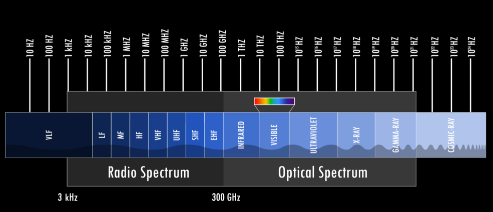
One thing that helps in gaining an understanding of how RF works is finding ways to see it work. Radio frequency electromagnetic fields are similar in many ways to much higher frequency energy, such as light. Just as buildings block some light and create shadows, they also block RF.
However, the shadows are not completely dark, as some light finds its way in by reflection from other objects and scattering in the atmosphere. RF behaves the same way, although the amount of reflection and scattering in the atmosphere will vary with frequency and wavelength, which is the frequency divided by the speed of light.
Comparing RF to Light
Like light, RF energy can be focused. In transmit antennas, this concentrates the power on the ground and can be used to target specific areas while avoiding others where coverage isn’t needed or interference has to be reduced. In receive antennas, the focusing provides gain, which, like a telescope, increases the intensity of the signal coming from one direction and reduces signals from other directions that may cause interference.
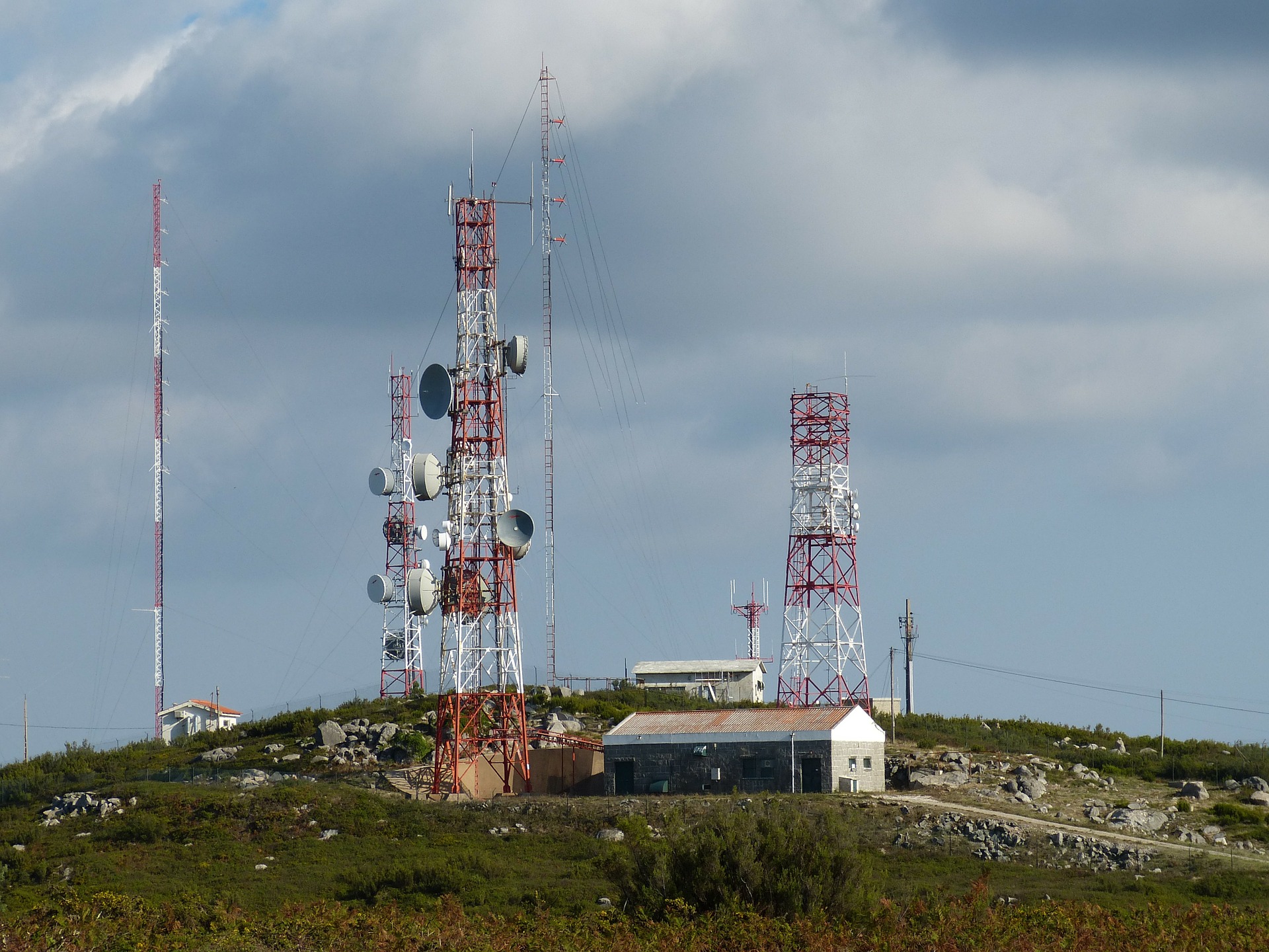
As RF frequencies increase and wavelength decreases to a millimeter or less, antennas can even start looking like optical devices. At satellite and microwave frequencies, parabolic reflectors are commonly used. These also turn out to be quite effective at light and infrared wavelengths, as anyone who has had an LNB cover melt when the sun moved behind the satellite the dish was looking at knows.
The professional video industry's #1 source for news, trends and product and tech information. Sign up below.
Antennas and Wavelength
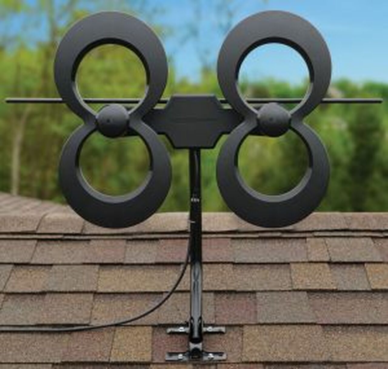
Keeping in mind the relationship between frequency and wavelength can also help in evaluating antennas. Antennas that have to work on lower frequencies, like low-band VHF-TV (54–88 MHz), FM radio (88–108 MHz), have to be larger than those used for high-VHF TV (174–216 MHz) or UHF TV (470–608 MHz) to work efficiently. This doesn’t mean small antennas won’t work at the lower frequencies for reception, just that the antenna itself will be less efficient.

One solution is to add an amplifier. However, the amplifier will add its own noise, reducing sensitivity, and because the small antenna will be less directional (focused) it will pick up more surrounding noise and interference. For best results, a low-noise amplifier should be located at the antenna where it can offset the loss in the line to the TV and provide a good match to the line.
On the transmit side, matching the resonant frequency and impedance of the antenna to the transmitter is more important. Without getting into the math, matching the impedance is like connecting two pipes of the same diameter together with the faucet on one end supplying water at the optimum rate for the pipe and the device (say, a turbine in this analogy) at the other end. The water flows smoothly with the least amount of loss.
The same analogy applies in a system with a transmitter, transmission line and antenna. However, if the impedance of the components isn’t matched, it will lead to excessive current (causing heating) and voltage (potentially causing arcing) at different points in the system, depending on wavelength.
Most broadcast systems are well-matched, unless the antenna is damaged so problems are more likely to occur when a connector starts to lose contact, increasing loss and heat leading to contamination in the line, perhaps due to carbon created by overheating from a bad contact.
In most cases failures will create a mismatch in the line, which can be located at the base of the tower either by sending a very short pulse up the line and looking for the time it takes for the return reflection, or sweeping the frequency across a band of frequencies (and different wavelengths) and looking at the time domain response across the frequencies. Because these measurements involve “sweeping” between frequencies, this is often called “sweeping the line.”
TV Antenna Specs Debunked
One of the things that bugs me when reading reviews for TV antennas or looking at ads is comparisons based on range in miles or antenna gains that include a built-in amplifier. More responsible manufacturers will include the gain of the antenna at different channels. Most are based on gain above an isotropic antenna (without going into details, a “perfect” antenna) as “dBi” rather than gain above a dipole or “dBd” (like a set of rabbit ears with total length of half a wavelength). Gain in dBi will be 2.15 dB higher than gain in dBd. Ideally the specifications will specify whether the gain is in dBi or dBd.

The range numbers in antenna ads should be ignored, as they eliminate too many factors, such as the height of the transmit antenna above ground. Just as light diminishes quickly after the sun sets, when the transmitter’s antenna is below the radio horizon the signal will drop off quickly. Read my TV Tech column “Estimating Coverage: Quick Analysis for Facility Mods,” for more information.
For a transmit antenna 2,000 feet above average terrain, the radio horizon is 63.3 miles away. As the signal drops off quickly beyond this distance (as with light past sunset) ranges of more than 70 miles only would apply from mountaintop to mountaintop or for very high transmitter sites.
Experimenting With RF
The best way to get comfortable with RF is to experiment with it. While difficult to do on the transmitter side (unless you are a licensed amateur radio operator) there is a lot that can be done on the receive side. Check out my article “Inexpensive Tools for RF Field Measurements” for more information.
The Airspy Software Defined Radio (SDR) is a great way to explore the RF spectrum. It cannot demodulate broadcast TV signals, but it will show the TV signal’s spectrum and signal strength. A handheld spectrum analyzer like the TinySA (read my column “tinySA: Finding Interference and Aiming Antennas”) is a great way to explore RF spectrum.
I got an email from a reader who was seeing some odd behavior picking up distant stations in Chicago. He was interested in trying out different antennas and locations, so I suggested he get a tinySA. He did and is now able to see how antenna type, orientation and location impact the signal. He noticed the ripple (“spikes”) and I explained those were due to reflections. With a bit of time and tinySA, he now understands more about TV reception than many people today who work in broadcasting.
A clarification: In my article “RF at the NAB Show—ATSC 3.0, Part 1” I said Saankhya Labs developed their multi-standard ATSC 3.0 tuner in cooperation with Coherent Logic. Vasanth Shreesha from Saankyha said, “The Saankhya ATSC 3.0 receivers use our own chipset (SL3000 or SL4000)” and they were not developed by Coherent Logic.”
Email me at dlung@transmitter.com. I try to answer all emails promptly, but if I’m busy and the email gets buried, I might miss it. If you don’t get a response within a week or so, email me again.

Doug Lung is one of America's foremost authorities on broadcast RF technology. As vice president of Broadcast Technology for NBCUniversal Local, H. Douglas Lung leads NBC and Telemundo-owned stations’ RF and transmission affairs, including microwave, radars, satellite uplinks, and FCC technical filings. Beginning his career in 1976 at KSCI in Los Angeles, Lung has nearly 50 years of experience in broadcast television engineering. Beginning in 1985, he led the engineering department for what was to become the Telemundo network and station group, assisting in the design, construction and installation of the company’s broadcast and cable facilities. Other projects include work on the launch of Hawaii’s first UHF TV station, the rollout and testing of the ATSC mobile-handheld standard, and software development related to the incentive auction TV spectrum repack. A longtime columnist for TV Technology, Doug is also a regular contributor to IEEE Broadcast Technology. He is the recipient of the 2023 NAB Television Engineering Award. He also received a Tech Leadership Award from TV Tech publisher Future plc in 2021 and is a member of the IEEE Broadcast Technology Society and the Society of Broadcast Engineers.

