A visual information source requires a transmission or storage medium to convey its message to the observer. The fidelity of transmission and reproduction of the message is closely related to and dependent on the available medium capacity and the manner in which it is used. In the digital world the medium capacity is expressed in bits per second. Sometimes it is erroneously expressed in MHz.
Figure 1. Six layers make up the MPEG video datastream architecture.
The goal of digital video compression is to represent an image with as low a bit rate as possible, while preserving an appropriate level of picture quality for a given application. Compression is achieved by identifying and removing redundancies.
The MPEG-2 techniques
The MPEG-2 compression system uses a combination of lossless and lossy techniques to reduce the bit rate. Taken separately, none of these techniques can provide significant data reduction. However, by using the right combination of several techniques, very efficient data reduction systems can be designed.
The lossless techniques are:
- Blanking removal: The horizontal and vertical blanking areas are not recorded or transmitted. They are replaced by short sync data specific to the application. A Rec. 601, 10 bits per sample, 4:2:2 bit-serial datastream has a bit rate of 270Mb/s. Removing the nonessential blanking data results in a reduced bit rate of 207Mb/s without affecting the picture quality.
- Discrete cosine transform (DCT): A mathematical process that converts spatial amplitude data into spatial frequency data. The image is divided into blocks of eight horizontal pixels by eight vertical pixels (lines) of luminance (Y) and corresponding color difference (CB and CR) samples. A block of 8×8 pixels is transformed into a block of 8×8 coefficients describing the signal amplitude at a particular frequency. Essentially, the signal is converted into one value for the DC component and 63 values for 63 frequencies. This process is equivalent to a spectrum analysis. The coefficients are read out sequentially in a zigzag fashion, block after block. The process is totally transparent.
- Variable-length coding (VLC): Also called Huffman coding and entropy coding. This technique assigns fewer bits to code frequently occurring coefficient values and more bits to others.
- Run-length coding (RLC): This technique relies on the repetition of the same data sample value to generate special codes that indicate the start and end of a repeated value.
There are two lossy compression techniques:
- Sample subsampling: An effective data reduction method resulting in a loss of picture resolution. It is applied to chrominance signals resulting in the 4:2:0 and 4:1:1 formats. A 4:2:2 bit-serial signal, with a reduced bit rate of 207Mb/s, can be subsampled by reducing the number of bits per sample to eight and adopting a 4:2:0 structure. The result is a 124Mb/s bit rate.
- Requantizing: This process assigns more bits to low frequency coefficient values and fewer bits to high frequency coefficient values.
The MPEG-2 data structure
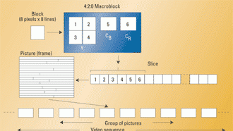
The MPEG-2 data structure is made up of six hierarchical layers. These layers are the block, macroblock, slice, picture, group of pictures (GOP) and the video sequence. Luminance and chrominance data are separated in 8×8 blocks of Y, CB and CR values. In a 4:2:0 format, macroblocks consist of four blocks of 8×8 Y values (16×16 pixels) and one block each of CB and CR values. A slice is made up of a number of contiguous macroblocks. The order of macroblocks within a slice is the same as the conventional television scan: from left to right and from top to bottom. Header values indicate the position of the macroblock within the picture and the quantizing scaling factor.
The picture is the primary coding unit in a video sequence. It consists of a group of slices that constitute the actual picture area. It also contains information needed by the decoder such as the type of coding (I, P or B) and the transmission order.
The GOP is made up of a sequence of various combinations of I, P and B pictures. It starts with an I picture which provides the reference for following P and B pictures and identifies the point for switching and tape editing. GOPs typically contain 15 pictures, after which a new I picture starts a sequence of P and B pictures.
The video sequence includes a sequence header, one or more GOPs, and an end-of-sequence code. The header contains information about the picture. The video sequence is known as the video elementary stream. Figure 1 shows the makeup of a 4:2:0 video sequence.
Intraframe compression
Intraframe (I) or static compression uses a combination of lossy and lossless schemes applied to the information present in the picture itself. As most television systems employ interlaced scanning, there is a temporal difference between the two consecutive fields. MPEG-2 allows pictures to be either a field or a frame, so there can be intrafield coding producing two pictures per frame. I pictures provide only moderate amounts of compression.
Figure 2. This conceptual block diagram shows an intraframe compression scheme producing I pictures.
Figure 2 shows a conceptual block diagram of a compression scheme producing I pictures. The full bit rate SDI 270Mb/s signal (4:2:2, 10 bits per sample) is first reduced to an eight-bit-per-sample, 4:2:0 representation before feeding the compressor. The input signal enters a spatial coder consisting of a DCT processor followed by a requantizer (REQ). The requantized DCT coefficients are read out in a zigzag fashion. The resulting long sequences of low amplitude, near-zero values are variable-length encoded (VLC) and subsequently run-length encoded (RLC). They are multiplexed with quantizing information and feed a buffer. The buffer controls the REQ to prevent the occurrence of overflow or underflow, and the result is a constant bit rate and variable picture quality.
Interframe compression and motion compensation
In a moving video picture most of the changes that take place from field to field are produced by an object moving from place to place or uncovering objects and picture area. When a picture area shows no motion, the best predictor for a pixel or block of pixels is the same group of pixels in the previous field or frame. In this case the prediction error will be zero or close to zero. VLC could be applied to reduce the bit rate. If there is motion in a picture area, simple prediction from the previous fields or frames will be incorrect and large prediction error values will increase the bit rate.
Figure 3. This interframe compressor generates forward-predicted P frames or bi-directionally predicted B frames.
This problem is solved by using motion compensation. This consists of a search within a confined region of the previous field or frame for the pixel or pixels that come closest to the current input signal. The digital information transmitted or stored consists of coded prediction error values plus the displacement vectors that locate the group of pixels in the previous field or frame. Motion compensation is used for a group of pixels, commonly a luminance (Y) macroblock consisting of four 8×8 pixel blocks. In most cases it is accurate to assume that all Y pixels, as well as the associated C B and C R pixels in a given macroblock, will experience the same displacements from one picture to the next.
Figure 3 shows a conceptual block diagram of an interframe compressor. It is a combination of intraframe and interframe encoders and can generate forward-predicted P frames or bi-directionally predicted B frames.
The predicted (P) pictures are coded with respect to the nearest previous I or P picture. The technique is called forward prediction. The output of the spatial coder feeds a spatial decoder that consists of an inverse REQ (IREQ) and an inverse DCT (IDCT). Its output simulates the output of a receiver decoder and feeds one of the inputs of an adder. The output of the adder feeds a future and a past frame delay. In the case of P frames, only the past frame delay is activated. The motion estimation block compares the present frame with the reconstituted past frame and feeds a predicted framestore. The output of the predicted framestore feeds the second input of the adder as well as the input subtracter. If the predicted P frame is identical to the present frame, the prediction error is zero and the bit rate is considerably reduced. If there is a prediction error, it is encoded by the spatial encoder and a motion vector is generated to indicate the correct position of the macroblock. Even if there is a prediction error, the bit rate is still lower than the original so there is a compression gain. However, coding errors can propagate between frames, since a P frame may be used as a reference to future P and B frames.
Figure 4. A sequence of frames comprise an MPEG group of pictures (GOP), one of the six hierarchical layers of the MPEG data structure.
The bi-directional (B) pictures use both future and past pictures as a reference. The technique is called bi-directional prediction. In this case both the past and the future frame delay are activated and their outputs are interpolated to generate the bi-directional predicted B frame. This process provides the most compression and does not propagate errors because a B frame does not serve as a reference.
The difference between an encoder capable only of P pictures and one capable of both P and B pictures lies in the available reference picture delays. Forward prediction requires the storage of only the past frame. Bi-directional prediction requires the storage of a past as well as a future frame.
Figure 4 shows a typical sequence of frames making up a group of pictures (GOP). A typical I, B, P MPEG-2 encoder can compress the Rec. 601 270Mb/s bit rate down to 8Mb/s without visible picture impairments.
Michael Robin, a fellow of the Society of Motion Picture and Television Engineers and a former engineer with the Canadian Broadcasting Corp.'s engineering headquarters, is an independent broadcast consultant located in Montreal, Canada. He is co-author of Digital Television Fundamentals, published by McGraw-Hill.
Home | Back to the top | Write us
Send questions and comments to:michael_robin@primediabusiness.com
