Performance testing is carried out by feeding a test signal to the input and measuring the distortions of the signal obtained at the output.
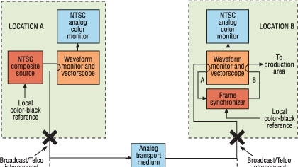
The term contribution implies that the signal is originated in a remote location “A” and is delivered to location “B,” where further analog signal processing, like mixing with other local signal sources, will occur. Figure 1 shows a typical analog contribution link setup.
Location A feeds the telco with signals meeting quality-control requirements as monitored on a waveform monitor, vectorscope and color monitor. At location B, the received signal is fed to input A of a monitoring/test package consisting of a waveform monitor, a vectorscope and a color monitor. Not shown in the diagram is an optional equalizing distribution amplifier between the telco interconnect point and the input B of the monitoring package. The signal is then fed to a frame synchronizer that stores the non-synchronous incoming signal in a digital memory. The memory is read out at the local sync rate producing video signals that are synchronized, timed and phased to match other local signal sources. This process is required to allow the mixing of the remote signal with locally generated signals. The output of the frame synchronizer feeds input B of the monitoring package and the production area.
The analog transport medium may be a coaxial cable, a fiber optic cable or a satellite system. It delivers the video signal to location B but also introduces video signal impairments. In the world of the NTSC analog video signals, the performance indicative parameters are grouped into three categories: linear distortions, nonlinear distortions and noise.
Performance testing is carried out by feeding a test signal to the input of the system under test and measuring the distortions of the signal obtained at the output of the system. For off-service test purposes the NTSC composite source is a video test generator feeding full-field test signals. Alternately, for in-service test purposes, selected test signals (VITs) are transmitted in one or several lines of the vertical blanking. The system under test is the analog transport medium under the responsibility of the telco organization. It is usual to divide the responsibilities by clearly identifying the interconnect points.
Years of accumulated experience, resulting in national and international standards, led to the development of test methods and equipment that uses a set of specific test waveforms. The various test waveforms stress the distribution medium, which reacts by distorting the test waveform. The measurement of the resulting distortion yields figures that clearly identify the source of trouble. The performance test philosophy is based on the fact that there is a direct and well-understood relationship between the shape of the test waveform (the medium) and the perceived picture quality (the message). To paraphrase Marshall McLuhan, the medium is the message.
The digital link
Figure 2 shows a suggested digital contribution link setup using MPEG-2 compression. As in the analog case, the term “contribution” clearly restricts the signal path to delivering digital signals that will be further digitally processed. Location A feeds the telco with a serial digital video source signal (SDI) at 270Mb/s, which meets the requirements of SMPTE 259M Standard. These requirements include p-p signal amplitude, rise/decay time, overshoot/undershoot and timing/alignment jitter. These signal characteristics are measured and monitored with a serial digital waveform monitor, which in turn feeds decoded G,B,R analog component signals to a component analog color monitor. The waveform monitor can display and measure the characteristics of the SDI signal (the medium) as well as the component analog Y, B-Y, R-Y signals (the message).
At location B the SDI signal delivered by the telco feeds input A of a digital waveform monitor and a frame synchronizer. Not shown in the diagram is an optional equalizing/reclocking SDI distribution amplifier needed to regenerate the signal in case a long coaxial cable feed. The frame synchronizer genlocks the incoming SDI signal to the station reference to match other locally generated SDI signals and eliminates timing and alignment jitter. While typical MPEG decoders may eliminate jitter, the ones I have encountered have no means to be genlocked to station reference, hence the need for a separate frame synchronizer. The output of the frame synchronizer feeds input B of the waveform monitor and the production area.
Prior to signing the contract with the telco company it is safe to carry out evaluation tests of the compression technology to be used including the transport medium if possible. The purpose of these tests is to obtain certain objective performance indicative figures, which reflect the performance of the system. Note that analog type test signals are unsuitable for testing digital systems and that VIT test signals are not passed.
The MPEG-2 encoding/decoding process generates artifacts whose degree of impairment of the perceived picture is directly related to the compression ratio. Figure 3 shows some of the compression related artifacts. Cost vs. performance considerations inevitably lead to choosing a link with the lowest bit-rate, which produces acceptable picture quality. By necessity, a high compression ratio will result in a lower picture quality. Here things get quite complicated. The acceptable picture quality is essentially a subjective concept. In analog video there is a well -defined and understood relationship between a distorted video waveform and the perceived quality of the resulting picture. In other words a distorted waveform means a poor picture. In the digital world the shape of the digital signal does not directly relate to the perceived picture quality. Essentially the digital waveform may be quite distorted while the perceived picture quality is excellent.
A number of manufacturers have developed objective picture quality measurement methods and equipment. In several instances I have used the Tektronix PQA200 system. This unit expresses the performance of the compression/decompression system under test in terms of PQR (picture quality rating) and PSNR (peak signal-to-noise ratio). The measurement philosophy is based on the JND (just-noticeable difference) concept developed by the Sarnoff Research Center. The method used compares the image fed to the input of the system with the one present at the output of the system pixel by pixels and expresses the difference in numbers that reflect the image degradation as perceived by the HVS (human vision system). This test requires simultaneous access to the input an output of the system under test. The performance level is expressed in PQR units related to the CCIR five-level impairment scale. PQR measurements can be carried out on the luminance signal only (PQRy) or on both the luminance and chrominance signals (PQRyc). PQRyc measurements require a longer time but offer a more complete analysis. In addition the unit performs PSNR measurements.
Various image sequences are available on CD-ROM disks. A test sequence lasts five seconds of which two seconds are used for analysis. From the large number of test picture sequences I have been using three namely: “Diva”, “BBC” and “Mobile with calendar” each with distinctive picture details and movement complexity: “Diva” is the less stressing and “Mobile with calendar” is the most stressing.
In addition to PQA tests, it is advisable to carry out several additional tests to determine the effects of the digital medium on the analog “message.” Among these tests are:
- Frequency response: Feed an SDI YCbCr multiburst sequence to the input of the system and verify that all packets are passing. This test verifies that all 704 luminance horizontal pixels and 352 chrominance horizontal pixels are passing through. A reduced number of pixels would affect the frequency response by cutting off high frequencies.
- Dynamic range: Feed an SDI limit ramp YCbCr signal to the input of the system and verify that all levels specified in CCIR 601 are passed. For an eight-bit system the dynamic range extends from 01h to FEh with a bottom headroom of 01h to 19h (black level) and a top headroom of EBh (white level) to FEh.
The hybrid link
In the transition period from analog to digital systems there are likely to exist some types of hybrid systems. A typical hybrid system would consist of a digital link with the following additional equipment:
- A/D converter: This unit converts the analog NTSC signal to an SDI signal feeding the input of the telco MPEG-2 compressor. For best performance it should feature a digital adaptive comb filter with full bandwidth luminance and chrominance signals.
- D/A converter: This unit converts the SDI signal at the output of the MPEG-2 decompressor to an analog NTSC signal. In addition it works as a frame synchronizer, eliminating the SDI jitter and genlocking the analog NTSC signal to station reference.
Michael Robin, a former engineer with the Canadian Broadcasting Corporation's engineering headquarters, is an independent broadcast consultant located in Montreal, Canada. He is co-author of Digital Television Fundamentals, published by McGraw-Hill.Send questions and comments to Michael_Robin@intertec.com
