The Humble Fresnel
There was some politics involved. The group of spotlights that we identify as "fresnel" derives their name from an early 19th-century scientist, Augustin-Jean Fresnel. As a result of his invention of this lens that has his name and its subsequent use to increase the visibility of lighthouse lights, he was appointed the French Commissioner of Lighthouses (enter politics).
He would be, of course, completely unaware and probably very astounded to know that his lens would become such a useful tool in entertainment lighting. He could have been the Commissioner of Lighting Designers. He might also be shocked to hear our initial attempts to properly pronounce (Fra-nell) his name.
THE IDEA
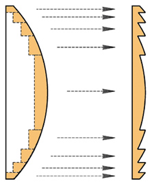
What Fresnel did was quite unique. He realized that, in a simple plano-convex magnifying lens, its optical beam-bending properties are caused by the curved surfaces of the lens and that most of the body of the lens can be removed to greatly lower the amount and subsequently the weight of the lens, but still retain the curved surfaces and their optical characteristics (Fig.1).

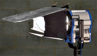
Fig. 1: Four-way eight-leaf barn door on a Fresnel spotlight
After doing this, the beam imaging is not as sharp, but rather soft and diffused. However, the light emanating from this new, lightweight lens still retains the basic directivity of the bundle of light "rays" that we would have in the simple lens we started with. It is this quality that makes the lens so desirable to lighting designers.
THE FRESNEL SPOTLIGHT
The beloved lighting instrument is very simple in form. The light emerging from the lamp filament is gathered by the lens and is able to be projected on a distant surface. The filament is located within a distance from the lens that is less than the focal length of the Fresnel lens and as a result, a virtual image of the filament is formed as the rays of light diverge.
Since only the light in a cone, which is a small portion of the light produced at the heated filament, is gathered, the efficiency of the device is low. It is increased by placing a highly polished spherical reflector to gather the light from the back side of the filament and focusing the light back to the filament plane.

Fig. 2: Fresnel lens basis The alignment of the reflector and the lamp filament is such that the reflected filament image is returned to the open spaces in the actual filament as a means to limit the heating of the filament. Some faith in the lamp and instrument manufacturer is required in order to accept that this rather tricky arrangement has been realized.
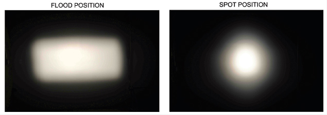
To "focus" the unit, the lamp and reflector are configured as one assembly and the projected light's size can be varied by moving the assembly relative to the lens. Typically the spot size will vary from a "flood" position where the image diameter is equal to the throw distance (1:1) to a "spot" position where the image diameter is about one-fifth the distance from the instrument to the lighted surface. The "flood" position is usually an angle of about 50 degrees.
EFFICIENCY
All is not perfect. The maximum efficiency of the instrument is in the flood position, where the lamp filament is closest to the back of the lens, and is only about 30 percent. In other words, only about one-third of the lumens (remember: lumens are light power) actually ends up lighting our subject.
The rest of the lumens are lost within the instrument and ends up as heat, which must be dissipated. In the spot position, the efficiency is much less, about 10 percent.
THE ATTRACTION
So what is the attraction of this optically compromised, soft-edged light? In common use a "barn door" accessory is used with the unit. We use this assembly of hinged flaps to alter the beam's lighting area. The edge that is produced by each flap not only limits the lighting area, but does it in a very useful manner.
The transition from lighted to unlighted is smooth and not too abrupt. Of great importance is that there is no spill from the lamp onto the unlighted area. But be cautious; a clean barn door cut is only obtainable when the unit is in the flood position. Spotting the unit up (or putting diffusion on the lens for that matter) will compromise the performance of the Fresnel spotlight. This is shown in Fig. 1.
BARN DOOR TECHNIQUE
In simple setup, as a single camera shoot, grip equipment can be easily utilized to restrict the lighted area from our spotlight. However, as space becomes limited and floor positioning is not practical as in a television multiple-camera shoot, the barn door may be a necessity as a substitute for an array of flags and cutters. So it becomes important to make this simple accessory as serviceable as possible.
The configuration I find best and most desirable is the four-door, eight-leaf unit in which two doors are solid while the width of the other two doors is adjustable. For the very common situation where a solid door is used to cut the top of the beam, the adjustable side doors' fins can then limit the side of the beam perfectly.

Fig. 3: Four-way eight-leaf barn door on a Fresnel spotlight and oven liner barn door extension I must add here that a barn door with four solid doors (four-leaf rather than eight-leaf) does not work satisfactorily and I wonder why it is so commonly offered.
It is also important that the cut of a door is not too far into the beam as to mask the center of the lens. This is mistakenly attempted in the case when a more defined cut is desired, resulting in seriously limited lamp output.
One easy solution (other than using a cutter) is to extend the barn door. A nice trick is to use a rigid piece of light aluminum sheet (say a supermarket oven-liner sprayed black) mounted to the door with a pair of spring clamps (Fig. 3). The adjustable side doors are then used to hold the (new) elongated solid door in place. Perhaps the unit is not so humble.
Bill Klages would like to extend an invitation to all the lighting people out there to give him your thoughts at billklages@roadrunner.com.
The professional video industry's #1 source for news, trends and product and tech information. Sign up below.
