Transmission lines Part 1
The professional video industry's #1 source for news, trends and product and tech information. Sign up below.
You are now subscribed
Your newsletter sign-up was successful
Many think of a transmission line as just overgrown video coax, but it’s more complex than that. The power levels of transmission lines are several magnitudes higher, which means that much more care and attention should be paid to them. The failure of a transmission line can result in the loss of hundreds or thousands of feet of line, which would have to be replaced, and would knock the station off the air.
Keeping an eye on your station’s transmission line and knowing its health is all part of maintaining a station’s transmitter and associated systems. How they work and what to keep an eye on is the topic of this tutorial.
What is it?
Transmission lines are used to transfer the RF power efficiently from a transmitter to the antenna, but they often are routed through high-power filters, switches and combiners on the way. The main parameters of a transmission line are its impedance, velocity of propagation, attenuation and its ability to handle power. Transmission lines can handle from tens to thousands of kilowatts of power, work in all types of weather and are basically simple devices that carry complex signals.
The type and size is determined by many factors such as frequency, effective radiated power (ERP), distance to be traveled and the type of tower the antenna is on. ERP is the power radiated by the antenna and is the number a station is licensed for by the FCC. Everything else at the transmission system has to add up to the licensed ERP. This starts with the transmitter power output less the losses from filters and transmission line and the gain of the antenna.
Rigid coax

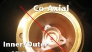
Coax is the most widely used transmission line, from cable TV to helix for higher power levels, while rigid coax is the most common type of transmission line in use for high-powered TV stations in the United States and is the subject of this tutorial. It consists of an inner conductor surrounded by an outer conductor, both of which are made of copper. With all the conductors aligned on the same axis, the conductors are coaxial, hence the word “coax.” Rigid coaxial transmission line has an inner conductor that is hollow like a pipe because AC electrical signals only travel on the outer surface of a conductor, which is called the “skin effect.” (See Figure 1.)
The professional video industry's #1 source for news, trends and product and tech information. Sign up below.
Coax transmission line comes in one of two impedances: 50Ω and 75Ω. The size of the inner conductor determines the impedance of the coax transmission line that uses air or nitrogen. A 6-1/8in coax with an inner conductor that is 2.6in OD has a 50Ω impedance, and one with an inner conductor that is 1.71in OD is 75Ω. So, the line with the larger inner conductor is 50Ω and the smaller one is 75Ω. (See Figure 2.)
Coaxial transmission line comes in sizes that range from 7/8in all the way up to 12in. The size of the line determines its power handling capability, with the largest ones capable of handling well over 100kW of power within the TV band. The limiting factor in coax’s ability to carry greater power levels is the rise in temperature of the inner conductor. Without a direct path to dissipate the heat generated from the RF passing through it, the inner conductor can overheat. If too much power is passed through a coax transmission line, the inner conductor will reach 621 degrees Fahrenheit, which is the melting point of the Teflon that is used to hold the inner conductor in place. Once that happens, the Teflon emits a gas that coats the inner conductor that insulates it further and causes the inner conductor’s temperature to rise even more. At some point, the Teflon will fail and the inner will sag, which causes a change in the impedance and arcing within the coax.
The power handling capability of rigid coaxial transmission line can be increased by over-pressurizing it. Normally, all rigid coax is pressurized to about 5PSI, which keeps any moisture out of the line. Moisture within a coax transmission line will lead to corrosion, voltage arcing and higher VSWR. But if the pressure is increased above this point, the gas within is compressed and makes for a better heat conductor, thus helping to dissipate the heat from the center conductor and increasing its power capability. Nitrogen is widely used to pressurized transmission line or, in some cases, dry air. Many facilities use bottled nitrogen to pressurize their transmission line, but nitrogen generators can be used for larger installations. These generators pull nitrogen directly from the surrounding air, which is made up of 78 percent nitrogen. Another option is air dehydrators that pass surrounding air through a desiccant that removes any moisture from the air; it is then pumped into the transmission line.
Using the flanges at each end, sections of rigid coax are bolted together, which provides a strong mechanical and electrical connection. The inner conductors are interconnected with bullets that are inserted into the ends of two adjoining line sections. To keep the inner centered within the outer conductor, Teflon disks, rods or pins are used along the length of the line to support it; any sagging would result in a change in the line’s impedance. It’s important to use the correct length sections of line for a particular frequency or channel because small discontinuities caused by the joining of two line segments occur at regular intervals, and that can create a filter and distort the transmitted signal.
Also, the round shape of rigid coax makes for less wind loading when mounted to a tower. Wind loading is an important factor in tower design and anything attached to it.
Making turns
Elbows are an important part of any transmission system, but they introduce their own discontinuities that affect the impedance and VSWR performance of the line. Elbows come in 90-, 45- and 30-degree angles, and non-standard elbows can be made. Usually placed just after any elbows or group of elbows is a set of line tuners that are used to smooth out the discontinuities introduced by the elbow. Some manufacturers have installed tuners directly in the elbow itself to make it easier to tune each one. (See Figure 3.)
Coax impedance
Impedance is a function of the ratio between the inner and outer conductors of a coax cable as well as the dielectric constant of the medium between them. For transmission line, the dielectric is air or nitrogen.
By knowing the size of the inner conductor, you know its resistance (R) and inductance (L). And by knowing the dielectric constance and the distance between the inner and outer conductors, you know their capacitance (C). This gives you the “R,” “L” and “C” of the coax, which enables you to calculate the impedance of the transmission line.
There are three important parameters for deciding on the impedance of a cable: voltage handling, power handling and attenuation. It has always been a trade-off between these three parameters when choosing impedance. Today’s standard values of 50Ω and 75Ω represent compromises between impedances found by Bell Labs to best fit the requirements of voltage, power and loss. Many other impedance values are in use, but these are the most common in transmission line.
Impedance that handles power well does a poor job at handling voltage and vise-versa. Today the choice is down to matching the impedance of the antenna, and 50Ω is the most common transmission line in use. In the past, 75Ω was more common when there was more concern about voltage and arcing. (See Figure 4.)
The 50Ω value was originally chosen for use in high-power RF due to a tradeoff. The high voltage used in high-power RF systems can lead to arcing in transmission lines when a mismatch occurs, such as a VSWR fault. In fact, the best impedance for voltage is 60Ω, but its power capability is very poor (less than 50 percent), so a compromise of 50Ω was chosen because it provided better power and good voltage handling capabilities.
If you could use 30Ω transmission line, you would be able to run your transmitter at half power and still make the same ERP. But at 30Ω, the transmission line’s voltage handling capability is compromised and almost any amount of VSWR would cause a breakdown, which would damage or destroy the line.
Next time
The next tutorial will continue the subject of transmission lines starting with waveguides.
