SFN Reception Could be Problematic With ATSC
The design of a single frequency network (SFN) must be based on the speed of light and the known performance of the Adaptive Channel Equalizers in existing DTV receiving devices, such as the 33 million NTIA-approved ATSC converters in use.
The speed of light is 300 meters per microsecond, so it takes 3.33 µS for signals to travel 1 km. Fig. 1 shows some ATSC receiver echo power vs. echo delay data. Leading echoes are those with negative delays; lagging echoes have positive delays. Leading echoes of 10 µS delay or less can be attenuated by many ATSC receiving devices and lagging echoes up to 40 µS delay can also be attenuated.
Lagging echoes are more the serious problem; however, adaptive channel equalizers can deal with lagging echoes better than with leading.
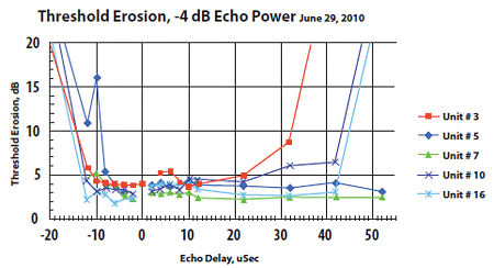
Fig. 1: Results of testing 5 NTIA-approved down-converters. An SFN might consist of three transmitters as in Fig. 2; up to seven as in Fig. 3; or up to 19 as shown in Fig. 4. Each of these figures shows a circle centered on a given transmitter site. These circles represent the minimum usable field strength for the ATSC signal.
In Fig. 2, these circles overlap. Within such areas receivers will see strong echoes, which some cannot cope with. That can be regained by increasing the radiated power of each transmitter, causing the circles to also overlap.
In the overlap areas, there are two signals of nearly equal field strength and almost zero relative delay. Receivers designed for DVB-T or ISDB-T signals love this, as the power of each adds constructively. ATSC receivers don't, as this modulation scheme doesn't allow such constructive addition.
The weaker of the two signals is a strong echo, of near-zero delay. You may wonder about the specific numbers of Tx in Figs. 2, 3 and 4. These numbers give the best coverage.
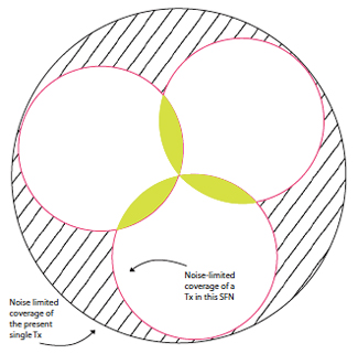
Fig. 2: An SFN with three transmiters. Note that their fields overlap.
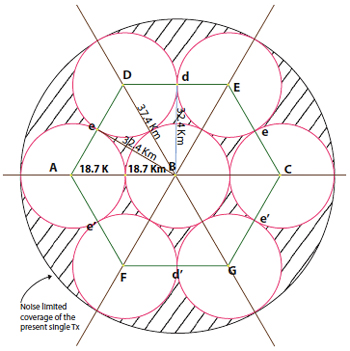
Fig. 3: A seven-transmitter SFN. Coverage areas don't overlap, resulting in significant loss of coverage when compared to that from a single transmitter. By increasing ERP, some coverage may be regained. However reception within overlapping areas depends on a receiver’s echo rejection.
For example, seven circles fill 78 percent of the area of a large circle representing the present coverage area of one transmitter as shown by the large circle around the SFM. If a large market needs more transmitters, up to 12 will fit within the next layer.
Some have considered even higher numbers of transmitters. We will discuss the seven-transmitter SFN in Fig. 3.
A typical TV tower is 1,200 feet HAAT, with a radio horizon distance of 49 miles. This is the real limit for noise-limited coverage and it amounts to 7,740 sq. miles or 20,000 sq. km.
In Fig. 3 the coverage of each transmitter would be on the order of 1,100 sq. km. Each transmitting antenna might be limited by the FCC to 75 m above ground. This would limit the undesired field strength in neighboring communities, which use the same channels. Table I gives this data for Figs. 2, 3 and 4.
In Fig. 3, I chose the radius of each "cell" the circle around each of seven transmitter sites as 18.7 km (about 12 miles), as TV signals travel 300 m per msec., or 0.3 km per msec. That means that it takes 3.33 µS to travel 1 km.
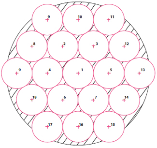
Fig. 4: SFN with 19 transmitters. Reception isn't possible in the shaded area without increasing ERP and creating overlap. Table II gives the distances from each of the seven transmitter sites of Fig. 3 to "points d and d," which behave exactly the same. Points such as "d and d" are not near the edge of the station's noise-limited coverage. They may occur where the population density is high, thus affecting many potential viewers since North American SFNs don't use COFDM.
One kW ERP is assumed for their field strength at points "d and d" are shown. The undesired signal from either D or E is nominally equal in power to the desired signal at points d (D/E = 0 dB). They are nominally have equal delay.
This echo can be removed by ATSC receivers with some cost in SNR. At point d, a second echo from transmitter B is present, which might jam reception at b on some receivers.
The echoes from transmitters A and C will be only 20 dB below the desired signal at points "d and d." Many receivers cannot handle such an echo as their power is an additional noise source. Their combined noise is 17 dB below the signal power. This suggests that these echoes can kill ATSC reception at points such as "d and d."
The echo from transmitter B is marginal at best for most NTIA-approved converters. Receiving devices may attenuate a 46 µS echo, but with a considerable loss in SNR. This is called echo desensitization of the receiver.
The 162 µS echoes from transmitters F and G cannot be attenuated by any receivers, so they combine to be treated as noise at 24 dB below the desired signal. In general, this seven-transmitter SFN would be unreliable at best.
If this SFN were redesigned with greater spacing between transmitters, the marginal echo (46 µS) would become a pathological case where reception would be expected to fail.
If this seven-transmitter SFN were redesigned with, say, 8 km between transmitters, it would probably cover a portion of the present service area, but not all. To rectify this, an outer ring of up to 12 transmitters may be required. (If the outer ring encompasses unpopulated areas, some of the 12 aren't needed.)
Active echoes generated by the six SFN transmitters arrive at most service area receive sites from different directions. These echoes could be discriminated against by means of a roof-mounted directional antenna. (SFNs using COFDM could constructively combine powers of delayed signals.)

Table I: Coverage area and radius for several SFN designs
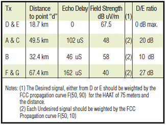
Table II: Distances and relative echo delays to points “d and d” of Fig. 2
Charles Rhodes is a consultant in the field of television broadcast technologies and planning. He can be reached via e-mail atcwr@bootit.com.
Comment on this or any story. Write totvtech@nbmedia.comwith "Letter to the Editor" in the subject line.
The professional video industry's #1 source for news, trends and product and tech information. Sign up below.
