SFN in an FMI Environment
The professional video industry's #1 source for news, trends and product and tech information. Sign up below.
You are now subscribed
Your newsletter sign-up was successful

I am currently running ATSC signals in my lab from a DTV test signal generator on loan from Rohde & Schwarz. It can also produce DVB-T signals. So, recently when I was in Germany, I bought a DVB-T receiver. Now I can simulate single frequency network (SFN) performance on both ATSC and DVB-T signals. If I had an ISDB-T receiver, I could test with the SFE generating ISDB-T signals too.
This inspired me to rebuild the 75 ohm RF signal distribution system in my laboratory. The Rohde & Schwarz generators can provide enough RF signal power to drive 32 DTV receivers simultaneously. Previously, I could only test 16; now I can test 26, as I currently have 26 ATSC receiving devices (NTIA-approved converter boxes).
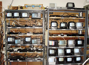
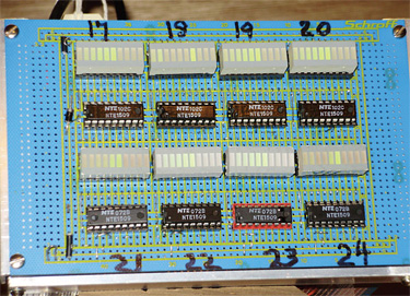
Fig. 1 shows 24 of the units and their monitors under test. Two more are being added. Fig. 2 shows the new eight-channel visual VU indicator, which augments the 16-channel visual VU indicator at the top of Fig. 1.
More important than the number of devices is the number of different IC chipsets in these devices. I understand there are 13 different IC chipsets in the NTIA-approved converter boxes.

Fig. 1: 24 test units in the author’s lab. I never opened up the boxes, but I've been told by someone with firsthand knowledge of them that, of the 13 chipsets, 11 exist in the converter boxes in my RF test bed.
Where are the missing two sets?
Possibly one or both approved units weren't put into production. So I feel comfortable that tests run in our new, improved facility with the SFE signal generator cover a lot of the DTV receivers in use in the United States today. The NTIA has reported that about 33 million coupons for converter boxes were redeemed by the public.
A CONSEQUENCE OF USING SFN?
This column has dealt with FMI (frequency modulation interference, or interference from an FM broadcast signal) to reception of VHF high-band DTV signals. In those tests we only had nine converter boxes. Very weak signals will not only exist at the noise-limited perimeter of a station, but also where an indoor passive antenna is used for DTV reception.
If we transition to SFN, a receiver equally distant from two or three transmitters in an SFN will be receiving two or three weak signals on the same channel at almost the same weak signal strength.
The population near the edge of the current noise-limited coverage is low; however, that won't be the case if we transition to an SFN topology in the United States. There will be lots of people living near the noise-limited coverage of multiple SFN transmitters.
One of our first tasks will be to test for FMI in a hypothetical SFN environment. Some have claimed that with an SFN, more people with have stronger signals. This is certainly true in Germany where they have three 20 kW transmitters serving an area with DVB-T signals.
At the recent Fall IEEE Broadcast Technology Symposium, one presenter suggested 5 kW transmitters would be adquate. Another speaker suggested that seven transmitters would be a reasonable number. So assuming that both are correct, that's 35 kW for a SFN configuration vs one megawatt for a single station serving the same community. The power difference between the combined SFN transmitters and the megawatt transmitter is about 15 dB. The average field strength of a SFN, if it were to be implemented in the United States, would have to decrease in order that co-channel spacings of transmitters could be reduced to permit all incumbent broadcasters to continue to with their very own channel.

Fig. 2: Eight-channel visual VU indicator, which augments the 16-channel visual VU indicator at the top of Fig. 1. One thing we've already learned from testing ATSC transmission in an SFN is that the phase of the echo is extremely important to the results obtained in a test. This isn't true for DTV signals that employ COFDM, but it is crucial for our ATSC system.
We're talking about echoes from the other transmitters of an SFN. They may be 40 km apart. The echo (the weaker of the ATSC signals) may be nearly as strong as the stronger signal. We call this a 0 dB echo.
It is, I believe, peculiar to SFN operation, as the FCC does not allow DTV transmitters allocated to the same channel to be less than about 200 km distant.
This distance may be 40 km, or even a bit less. That would result in co-channel interference, unless the receiver's adaptive channel equalizer can reject the weaker signal (the echo).
If the phase of an ATSC signal and its echo in an SFN differ by about 180 degrees at the pilot carrier frequency, the signal power and the echo power may sum to nearly zero power. The pilot dies and we have seen many of the 2008-vintage converter boxes die when we set the phase to cancel the pilot carrier.
In our laboratory, we manually adjust the echo phase to cause maximum attenuation of the pilot carrier of the test channel. Without such precautions, one can get a wide range of echo rejection.
Charles Rhodes is a consultant in the field of television broadcast technologies and planning. He can be reached via e-mail at cwr@bootit.com.
The professional video industry's #1 source for news, trends and product and tech information. Sign up below.
