Auto-negotiation's role in plug-and-play
As engineers who maintain professional media networks, we may plug in hundreds or even thousands of Ethernet RJ-45 cables during our careers. In almost every case, the links just work. Understanding how we are able to interconnect 10Base-T, 100Base-T and GigE devices is worth knowing, especially when devices do not behave as expected.
Interoperability
In the early days of computer networks, a number of different cable mediums were tried, including RG-11 coax, RG-59 coax and Unshielded Twisted Pair (UTP). In the end, UTP and the RJ-45 connector won out over other alternatives. At the same time, Ethernet became the dominant networking technology. (There were other early networking technologies such as ARC-Net and Token Ring, but in almost all cases, these were dropped in favor of Ethernet.)
The first widely deployed Ethernet technology was 10Base-T, operating at 10 Mb/s. 10Base-T can operate either half-duplex (meaning that a Network Interface Card (NIC) can send or receive, but not at the same time), or in full-duplex (meaning that NIC cards can send and receive simultaneously). 10Base-T networks were deployed all over the world. But, even as 10Base-T was rising to become the dominant networking technology, designers came up with a faster network known as 100Base-T, capable of running at speeds up to 100Mb/s. And, of course, now we have GigE, or 1000Base-T, running at 1Gb/s. All of these standards support either half-duplex or full-duplex operation.
Today, plug a variety of computers, network switches and other networking devices into a wired Ethernet network, and they all pretty much just work. But, what makes this possible?
Link integrity
A fundamental concept in 10Base-T is link integrity. To establish whether a connection was live or not, 10Base-T included the regular transmission of the Normal Link Pulse (NLP). NLPs were sent every 16ms. This heartbeat pulse was used as the basis for a Link Integrity Test (LIT). If a receiver does not receive either an NLP or a data packet within 50ms to 150ms, then the NIC enters the link fail state. This disables the sending and receiving of packets. But, importantly, the NIC continues to send NLPs. When the problem is corrected, and the receiver begins receiving NLPs, or packets, the NIC clears the link fail state.
This approach allowed applications to quickly determine if a network connection was alive or dead. But, the LIT did nothing to help when one NIC card was configured for half-duplex and the other for full duplex.
The professional video industry's #1 source for news, trends and product and tech information. Sign up below.
With the introduction of 100Base-T, the number of combinations and permutations available when connecting a device to a network increased. After all, you could have two devices operating at 100Base-T, one device operating at 10Base-T and another operating at 100Base-T, and so on. This is not to mention whether the devices were in half-duplex or full-duplex mode. How could designers ensure that end users could simply connect two devices and have them talk?
Auto-negotiation
The solution was to come up with a way for the two devices to communicate their capabilities. It was decided to use the space between NLPs to transmit a fast link pulse (FLP). The FLP is a string of 33 positions, occupied alternately by clock pulses and data pulses. Once a connection is established, NICs cease to transmit the FLP. The FLP contains, among other things, a technology ability field and an ACK bit. Using the FLP, an NIC can signal its highest capability. For example, one NIC might signal that it can operate at 100Base-T, full-duplex. The other NIC may signal that it can operate at 100Base-T, half-duplex.
Once the technology ability field is received, an NIC looks at a Priority Resolution Table and selects either its highest priority capability or the capability of the other card, whichever is lower. Here, the card would send a revised FLP, indicating 100Base-T, half-duplex and an ACK. Both cards would cease transmitting FLPs, and the link state would be set to UP.
Auto-negotiation capability is optional for 100Base-T cards, but it is mandatory for 1000Base-T NICs. In addition to negotiating speed and duplex settings, auto-negotiation is used to establish a master-slave relationship between two devices. The master-slave concept was added in the 1000Base-T standards.
Practical application
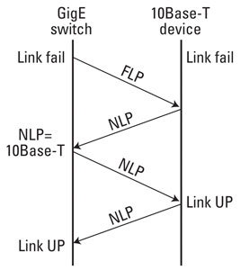
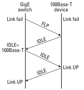
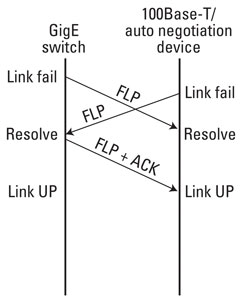
So, how does this work in the real world? Rich Hernandez lays out some great examples in a paper titled “Gigabit Ethernet Auto-Negotiation,” published by Dell. Let’s take a look at his three cases. In the first one, you connect a 10Base-T half-duplex device to a GigE switch. In the second case, you connect a 100Base-T half-duplex device to the same switch. In the last example, you connect a 100Base-T auto-negotiation capable device to the GigE switch. Remember, the first two devices do not have auto-negotiation capabilities. Let’s look at some diagrams that will help illustrate what is going on as each pair negotiates a link.

Figure1. A GigE switch is connected to a 10Base-T half-duplex device.
In the first case, both devices begin in a link fail state. (See Figure 1.) The GigE switch begins sending Fast Link Pulses. The old 10Base-T device begins sending NLPs. When the GigE switch receives the NLPs, it immediately hands off negotiation to a legacy 10Base-T Physical Medium Attachment module.
From this point on, the GigE switch behaves as if it were a legacy 10Base-T device. It begins sending NLPs. Both devices detect NLPs and transition from link fail to link UP state. As Hernandez notes, the default condition when a GigE device detects a 10Base-T device is half-duplex. If the 10Base-T device is set to full duplex, it will not work.

Figure 2. A 100Base-T device without auto-negotiation is connected to a GigE switch.
In the second situation, we are connecting a 100Base-T device without auto-negotiation to a GigE switch. (See Figure 2.) Again, both devices begin in a link fail state. The switch begins transmitting Fast Link Pulses. At the same time, the device, which knows nothing about FLPs, begins transmitting idle symbols. The GigE switch detects the idle symbols and immediately knows that it is trying to negotiate with a 100-Base-T device. As with the 10Base-T device, only half-duplex is supported when a GigE device is establishing a link with a non auto-negotiation device.
The GigE switch begins sending out idle symbols, both devices then recognize the other, and they change their status from link fail to link UP.

Figure 3. This shows a case where both devices are auto-negotiation capable, but with a speed mismatch.
In the final case, both devices are auto-negotiation capable, but there is a speed mismatch. One is a 100Base-T device, and the switch is GigE. Figure 3 shows that the devices begin in link fail. Both of them transmit FLPs. The highest capability of the 100Base-T device is 100Base-T, full duplex. Both devices recognize that this is the fastest, shared capability mode, so the GigE switch configures itself for 100Base-T full-duplex. At that point, the devices change state from link fail to link UP.
Errors
When auto-negotiation works, it works well. But, problems can arise when a GigE switch expects a slower device to be in half-duplex mode and it is instead in full duplex. When this happens, links may either become extremely slow, or they may not work at all. It is critical that engineers who maintain professional media networks understand that incorrect duplex configurations in older equipment can cause serious performance problems.
The root of the issue is in the original Ethernet collision and backoff method of sharing a single piece of media. There is no guarantee in Ethernet that two cards will not try to talk at the same time. When they do, both cards detect a collision, stop transmitting and then retry after a random period of time. In a multiplex mis-configuration situation, the card in half-duplex detects a collision and retries. The full-duplex card does not retry, but it does detect that the incoming packet is bad and discards it. So, be sure you configure cards correctly.
Looking ahead through the coming months, we will explore additional basic networking concepts.
—Brad Gilmer is executive director of the Video Service Forum, executive director of the Advanced Media Workflow Association and president of Gilmer & Associates.
