The Perils of Putting TV Stations in the Duplex Gap
The professional video industry's #1 source for news, trends and product and tech information. Sign up below.
You are now subscribed
Your newsletter sign-up was successful
Click on the Image to Enlarge
Click on the Image to Enlarge
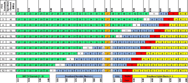
In 2014 the FCC published details on how it will configure the 600 MHz Band. The 11 scenarios under consideration are shown in Fig. 1: TV channels are shown in green, base station transmissions will be on 5 MHz wide blocks shown in blue, and cellphones will transmit on blocks shown in yellow.
Fig. 1

A call originates from a cellphone transmitting on one of the yellow blocks, say Block F. A base station would reply also using Block F shown in blue.
This so-called “duplex system” that allows both parties to talk at the same time, requires that the base station transmit on a different block of frequencies (blue block) than a caller transmits on (yellow block). Both will use the same letter code. This duplex system illustrates how phone services have always worked.
‘BRICK WALL’ FILTER NEEDED?
Both base station and cellphone user equipment have a filter called a “frequency duplex filter” or “frequency diplexer” between the antenna and the transmitter output and receiver input. An incoming signal passes to the receiver from the receiver port of this filter, and when transmitting, its signal is routed to the antenna and not to the receiver input.
Here is the problem: Suppose the base station transmits on 600–602.5 MHz, while the cellphone transmits on 602.5–605 MHz. That would be a very efficient use of spectrum, but the duplex filters in both the base station and the cellphone would have to be “brick wall” filters—flat across their passbands and zero outside of the passband. Physics decrees that such a filter cannot be designed. Yes, it can be approached by using many poles, but such a filter is too large and too heavy for a cellphone, and by the way, its insertion loss would be unacceptable as it would reduce receiver sensitivity and battery “play time.”
The professional video industry's #1 source for news, trends and product and tech information. Sign up below.
But suppose there is a gap between the two blocks. Say the upper edge of the blue block is 600 MHz and the lower edge of the yellow block is 611 MHz. A very simple filter can be designed for this duplex gap between transmit and receive signals. This filter’s transition bandwidth of 11 MHz wastes spectrum because there should be no signals allowed within a duplex gap, but that is the price that must be paid to make wireless phones possible.
WIRELESS COULD SUFFER, NOT BROADCASTERS
That was the way it was until recently. Many stations volunteering their 6 MHz channel hope to receive up to $120 million; approximately $20 million per MHz per community. Some in Congress questioned the $220 million loss of revenue that results from these 11 MHz duplex gaps. Recently, the FCC has reported that in a “few unidentified communities,” it will have to place DTV stations within a duplex gap.
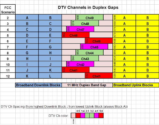
Each full-power TV station in the 600 MHz band radiates an average power of 1 million Watts, while a cellphone radiates a maximum average power of approximately 0.005 W. Base stations can radiate up to 720 W average power in 6 MHz bandwidth. As shown in Fig. 2, depending on what frequency scenario the FCC decides for a given community, a DTV station allotted a channel in the duplex band gap may end up centered in the duplex band or may be positioned hard against an edge of the wireless band as illustrated in scenarios 6 and 12.
The megawatt of power radiated within a UHF channel is accompanied by up to 34 W of sideband splatter (noise) falling in each adjacent channel. With an ATSC signal within a duplex gap, this legally radiated sideband splatter falls into either a base station block (blue area in Fig. 1) or a cellphone transmitter block (yellow areas in Fig. 1).
Fig. 2

Fig. 2 shows that a full power station in three of the 11 scenarios can jam blue blocks 5 and 11 or yellow block A. DTV signals in the duplex gaps of three other scenarios: 4, 10, (in magenta) and block A (yellow) can to a slightly lesser extent jam LTE signals in the 600 MHz band. Note that it is the wireless operators who will suffer, not broadcasters. In Fig. 2, I have placed the ATSC signal on the FCC standard TV channel frequencies within the 11 MHz duplex gaps. At first, I thought to center these ATSC signals in the duplex band gaps, but that won’t work. My colleague, Linley Gumm and I found by testing, that modern DTV receivers cannot lock to an ATSC signal which is not at the FCC standard channel frequency. A few receivers tolerated a displacement of about 1 MHz, but certainly no more than that.
You may be thinking: Why should broadcasters be concerned that placing TV signals in these duplex gaps may harm wireless transmissions? Well, in my next article, I plan to discuss the effect of placing a 1 Megawatt TV signal between TV spectrum (green in Fig. 1) and base station transmitter frequencies (shown in blue). Broadcasters and broadband operators will both see RED if there are TV signals between the green and blue areas of Fig. 1.
I wish to acknowledge the work of my colleagues, Linley Gumm and Stanley Knight which underlies the writing of this column for almost a decade.
Charles Rhodes is a consultant in the field of television broadcast technologies and planning. He can be reached via e-mail at cwr@bootit.com.
