The FCC’s DTV Interference Dilemma
The professional video industry's #1 source for news, trends and product and tech information. Sign up below.
You are now subscribed
Your newsletter sign-up was successful

Charles W. Rhodes By now, almost everyone knows the National Association of Broadcasters is suing the Federal Communications Commission over rules for the TV spectrum auction and channel repack in 2016. This suit concerns the procedures by which the FCC will calculate the number of persons affected by co-channel (CC) and/or adjacent channel interference (ACI).
There is another class of interference by undesired (U) signals on other channels. Some of these are known from the days of analog TV in the UHF band as taboo channel interference (TCI). Recently we covered interband interference (IBI), which always involves two or more U signals.
About four years ago this column discussed a specific kind of IBI, frequency modulation interference (FMI). The second harmonics of FM radio signals (88–108 MHz) fall in the high VHF band (174–216 MHz). When the tuner of a DTV receiver is overloaded by one strong FM radio signal, only the second harmonic of that FM signal can cause jamming of a VHF signal on Chs. 7–13. When there are two strong FM signals, the second harmonics of each may be generated in the tuner of DTV receivers. In addition to these harmonics new frequencies will also be generated in the tuner.
These are of the form 2*Fa–Fb and 2*Fb–Fa; and two other third-order inter-modulation products (IM3), which are also generated (2*Fa+Fb and 2*Fb+Fa). The latter do not fall in any of our TV bands so they are usually ignored in the literature, but these can cause IBI. As you see, FMI is one form of IBI. This column recently showed that two strong high VHF band (174–216 MHz) signals may generate IM3 of the form 2*Fa+Fb and 2*Fb+Fa that fall in the portion of the UHF band that will remain broadcast spectrum after repacking.
What if there are three high VHF band signals (Fa, Fb, and Fc)? These generate IM3, which fall in the UHF band:
2*Fa+Fb, 2*Fb+Fc, 2*Fc+Fa
2*Fb+Fa, 2*Fc+Fb, 2*Fa+Fc
They also generate another class of intermodulation products: triple beats (TB). These are of the form Fa+Fb +/–Fc. If all three signal frequencies are additive, the TB frequency is about three times higher in frequency—and in the case of three high VHF signals—the TBs fall in the UHF band.
The professional video industry's #1 source for news, trends and product and tech information. Sign up below.

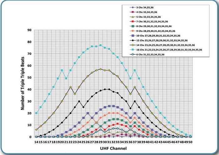
Fig. 1: Number of triple beats per channel for various allocations
Now let us look at TBs generated by three strong U signals in the UHF band. These are of the form: Fa+Fb–Fc, Fb+Fc–Fa and Fc+Fa–Fb. Note that any one of these can be subtracted from the sum of the other two. Fig. 1 shows the number of TBs for a range of U signals involved.
Four signals generate 10 TBs. For example, consider U signals on Chs. 33, 34, 35 and 36. The spectrum of these IM3 extends from Chs. 30–39 (581 + 587 – 599 = 569 MHz, Ch. 30). 608 plus 602 – 584 = 626 MHz (Ch. 39) as shown in Fig. 1:
• Five U on Chs. 32–36 produce 13 TB (Ch. 28–40);
• Seven U on Chss 31–36 produce 19 TBs (Ch. 24–41).
Each TB has about 6 dB more noise power than an IM3 being generated by these signals.
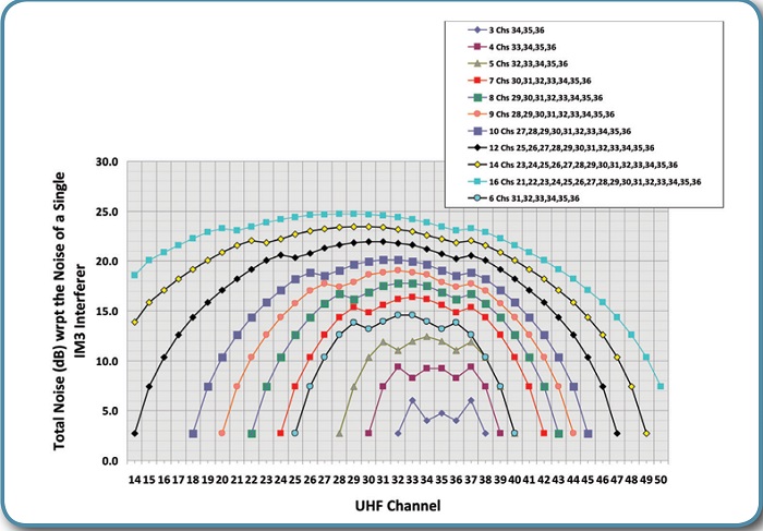
My colleague Stanley Knight ran these calculations and also plotted the total noise power in each channel by the IM3 and TBs for each set of U channels as shown in Fig. 2. This needs some further explanation.
Starting with four U signals on Chs. 33–36 there are 10 TBs and a smaller number of IM3. Both TBs and IM3 occupy three consecutive channels. The upper side channel and the lower side channel are about 6 dB weaker than the center channel of an IM3. We found that the noise in Ch. 30 is 3 dB greater than IM3, but Chs. 32 and 34 suffer 9 dB of noise. Ouch!

Fig. 2: Noise power spectrum of triple beats and their sides, and IM3 beats and their sides relative to the noise of a single IM3 interferer per channel for various allocations
Now look at the curve for seven U channels (30–36). The noisiest channel has a noise floor 16 dB above what a signal IM3 would have produced.
The reason why there is so much noise dumped into channels by a large number of U signals is that the number of TBs grows almost exponentially with the number of U signals. This is shown in Fig. 2.
RECEIVER DESENSITIZATION
That is the larger half of the misery. The smaller half is due to desensitization of DTV receivers when there are strong (overloading) U signals present. Desensitization results when the wide band AGC System (widely if not universally used in all DTV receivers, not just ATSC receivers), senses the mixer is being overloaded by the total power of multiple strong U signals, and thus, lowering the gain of the RF amplifier. But of course this also attenuates the desired (D) signal power at the mixer. That is automatically compensated for by increased IF amplifier gain. Alas, the increased IF gain also means that mixer noise at the second detector is increased and there goes the signal-to-noise ratio. If it goes below 15.2, dB reception fails.
CONCLUSION
While the FCC certainly intends to take into account the effects of CCI and ACI in its planning for repacking, it will not take into account any of the other forms of interference. This column has shown that there are many forms of interference other than CCI and ACI for DTV receivers. You might say that DTV receivers should not use this wideband RF AGC System. However, it must be used to meet the ACI limits, which the FCC has rightly imposed.
Since about 2012 most DTV receivers have a tuner built on a silicon chip and IC. This greatly restricts the RF selectivity of modern DTV receivers. You just cannot put high Q factor inductors on a chip.
Someday a new technology for fabricating filters may come into use in consumer products such as DTV receivers, but there is an existing population of nearly 100 million modern ATSC receivers out there. Perhaps 25 million of those receive signals from an antenna at the residence. How many of them will lose one or more channels due to interference that the FCC had to ignore to proceed with its mandate from Congress to auction TV spectrum for the public good? It is possible that the NAB may choose to amend its suit to add some of the other sources of interference in its lawsuit or others may also sue. Stay tuned.
Charles Rhodes is a consultant in the field of television broadcast technologies and planning. He can be reached via email atcwr@bootit.com.
