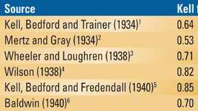
Table 1. Several different numerical values have been reported for the Kell factor — variations probably caused by differences in picture display systems, and subjective picture quality appreciation.
The 1930s witnessed an unprecedented technical de velopment frenzy in television. In the United States, in 1933, RCA had developed a 180-line, progressive scan, 24Fps all-electronic system. In a paper published in 1934 by Proceedings of the Institute of Radio Engineers, RCA Engineers R.D. Kell, A.V. Bedford and M. A. Trainer described an experimental television installation located in the Empire State building.
Initially, the camera used a Nipkow rotating disc with 120 scanning lines. This camera was later replaced by an all-electronic camera using an iconoscope and 180 progressively scanned lines. While experimenting with different types of static pictures containing horizontal and vertical wedges of increasing detail it was realized that the vertical spatial resolution rarely equalled the number of active lines. It was determined that, statistically, the vertical resolution equalled 64 percent of the number of active lines. To achieve the desired vertical resolution the number of scanning lines was increased to 240, resulting in a bandwidth of 600 kHz. The 0.64 figure was called the k factor and was later rounded up to 0.7. Eventually it came to be called the Kell factor. It could have just as well been called the Bedford or the Trainer factor.
The IRE paper further details the synchronizing pulses, the electrical signal, the video amplifiers and the transmitter. This early scanning standard was unsatisfactory because of excessive flicker due to the low number of 24 progressive frames per second.
Various writers have reported different numerical values for the Kell factor (see Table 1). The variations from one source to another are probably attributable to differences in the picture display systems used by different observers, as well as subjective picture quality appreciation.
Figure 1. The camera and CRT scanning spot shape and size affect the vertical resolution of the television picture. As the number of scanning lines goes up, so does the quality of the reproduced picture. Vertical resolution cannot exceed the number of active lines.
It is interesting to note that, contrary to what some people think, the Kell factor concept was initially related to progressive scanning simply because interlaced scanning had not been invented yet! So the Kell factor simply reflects the combined camera/CRT capture/display ambiguities, which affect equally the progressive and interlaced scan formats!
Figure 1 illustrates the effect of the combined effects of the camera and CRT scanning spot shape and size on the vertical resolution of the television picture. It is evident that the larger the number of scanning lines, the better the quality of the reproduced picture. The vertical resolution can evidently not exceed the number of active lines. But can it equal it? Figure 2 shows an ideal case when the number of active lines equals the number of vertical details in the picture. With camera-generated signals this is practically impossible to achieve because there is no way to ensure the details will constantly line up with the spot scanning structure. Most of the time, as shown in Figure 3, the spot will straddle the picture details, resulting in a loss of vertical resolution. The Kell factor merely expresses this vertical resolution uncertainty. Remember that we have been dealing with progressive scanning until now.
Figure 2. Vertical resolution equals the number of active lines when the raster lines are centered on the picture details. It is nearly impossible to achieve a vertical resolution equal to the number of active lines when using camera-generated images.
Towards high-definition television
By 1934 RCA had introduced a new, higher-definition scanning format. The number of scanning lines was now increased to 343 and the scanning was interlaced, and the picture repetition frequency was raised to 60 fields/s (30Fps). The interlace was rather poor because there were no equalizing pulses. By 1938, the number of scanning lines was increased to 441, interlaced, with pre- and post-equalizing pulses and excellent interlace. The transmission channel was now standardized to 6MHz with a full video upper sideband and a vestigial lower sideband, the video modulation was negative, and the audio modulation was FM. By 1941 the number of lines was increased to 525 and the FCC approved the system, which was called NTSC. Very few things have changed since then. It is to be noted that this system, a precursor to the post-war European 625-line system, was now based on the Kell factor in an effort to achieve equal horizontal and vertical spatial resolution.
In the UK, the 1920s legacy, the Baird electromechanical capture and display system, reached a picture format of 240 lines progressively scanned with a huge Nipkow wheel. For a while, in 1936, this system was alternated on a daily basis with an all-electronic system developed by Marconi-EMI. The Marconi-EMI system had a scanning format of 405 lines interlace scanned, 50 fields/s (25Fps). The interlace was rather poor because there were no equalizing pulses. The transmission was double sideband, positive modulation and the audio modulation was AM. By 1937 the BAIRD system lost to Marconi-EMI. By 1939 there were some 20,000 home receivers in use in the London area. The transmission ceased in 1939 at the beginning of the war and restarted in 1946. The same standard was kept except that the VHF spectrum was organized into 5MHz channels featuring a full lower sideband and a vestigial upper sideband. Transmissions in this standard ceased in the 1980s.
Figure 3. A loss of vertical resolution results from scanning spots straddling picture details.
Progressive vs. interlaced scanning
In addition to the spatial vertical resolution limitations, which it shares with progressive scanning (equal Kell factor), the interlaced scanning introduces its own peculiar artifacts. Movement-related artifacts result in “judder.” This effect is added to other related effects such as film-related stroboscopic effects, popularly known as “the wagon wheel effect,” and the 3/2 process of film-to-video transfer. Progressive scanning is unaffected by judder but keeps the other two effects.
A special interlaced scan spatial resolution problem, called interline flicker, occurs when sequential lines, in alternate interlaced fields, contain a great deal of vertical detail, as shown in Figure 2. This is unlikely to occur with camera-captured pictures, except sporadically. Interline flicker is 30Hz (25Hz in Europe) and, when present, is visible when the viewing distance is less than six times the SDTV picture height (three times for HDTV). In the 1930's this was considered a small price to pay for the reduced transmission bandwidth. The only signal source that will consistently generate interline flicker is the character generator. Progressive scanning displays are unaffected by interline flicker, but require twice the video signal bandwidth. The large area flicker frequency for both progressive and interlaced television is 60Hz (50Hz in Europe).
Computers use progressive scanning and high picture repetition rates to avoid interline flicker and large area flicker. Their vertical resolution is equal to the number of active lines. This is due to the fact that the computers, unlike cameras, can assign individual brightness values to each individual scanning line.
Interlaced scanning is just about 70 years old and used by all SDTV 4:3 aspect ratio formats. Is it a compromise? Definitely, but a very popular one if we consider the huge number of television receivers used throughout the world. In conclusion, is progressive scanning superior to interlaced scanning? The answer is definitely yes! Is there a definite trend towards progressive scanning in broadcasting equipment? Here there are many things to consider including the fact that the ATSC has left the choice to the broadcaster. It is the marketplace that will decide how things will develop, and at what pace and price.
References
- Kell, Bedford and Trainer, Experimental Television System - The Transmitter, Proc. IRE, vol.22, pp. 1248-1265, 1934.
- Mertz and Gray, Theory of Scanning and Its Relation to Characteristics of Transmitted Signal in Telephotography and Television, Bell System Tech. J., vol. 13, pp. 464-468, 1934.
- Wheeler and Loughren, Fine Structure of Television Images, Proc. IRE, vol. 26, pp. 540-575, 1938.
- Wilson, Channel Width and Resolving Power in Television Systems, J. Television Soc., vol. 2, part 2, pp. 397-429, 1938.
- Kell, Bedford and Fredendall, Determination of Optimum Number of Lines in Television Systems, RCA Rev., vol. 5, pp. 8-30, 1940.
- Baldwin, Subjective Sharpness of Simulated Television Images, Proc. IRE, vol. 28, pp. 458-468, 1940.
Michael Robin, a fellow of the SMPTE and former engineer with the Canadian Broadcasting Corp.'s engineering headquarters, is an independent broadcast consultant located in Montreal, Canada. He is co-author of Digital Television Fundamentals, published by McGraw-Hill.
Send questions and comments to:michael_robin@primediabusiness.com
