Implementing CALM in Live or Production Environments

MARY GRUSZKA As live audio mixers or post-production editors, we are accustomed to using VU meters or peak program meters (PPMs) to set and maintain desired levels. But now with the CALM Act on the books, 0 VU or –20 dB FS isn’t enough.
We need to ensure that the predetermined target loudness level is correct right at the source, and that means reading LKFS— or loudness, relative to full scale—and measured with equipment that implements the algorithm specified by ITU-R BS.1770.
SPEAKING FROM EXPERIENCE
In other words, we now need loudness meters in our audio control rooms and editing booths and the knowledge of how to use them. But it shouldn’t be that hard, atleast based on NBCUniversal’s experience.
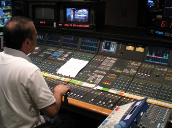
The company has equipped its live audio mixing rooms with loudness meters, placed in clear sight of the mix engineer. In addition, for post production, NBCU has upgraded the previously existing rasterizer displays in edit rooms with audio loudness monitoring capabilities and trained editors on loudness management practices. (The rasterizer displays also include video parameters and conventional audio VU and peak monitoring displays available to the editor.)
As would be expected, there was a learning curve, but not a steep one, according to Jim Starzynski, director and principal audio engineer for NBCUniversal Advanced Engineering, and chairperson of the Advanced Television Systems Committee (ATSC) technical subgroup S6-3 on digital television loudness.
The key is to set the level for the anchor element so it meets the correct target loudness level. In most cases, although not all, the anchor element is normal-level dialog (not shouting, nor whispering).

Table 1: Categories of audio mixing rooms and reference sound pressure levels (adapted from ATSC A/85). In the case of NBCU, “this anchor is mixed to the established target value of –24 LKFS,” Starzynski said. “Music and effects are blended with the anchor, each at a unique loudness that yields a natural sounding mix with appropriate dynamic range and intelligibility.”
The professional video industry's #1 source for news, trends and product and tech information. Sign up below.
It’s important to recognize that loudness measurements are not instantaneous, but must always be averaged over time.
“When mixing in real time, NBCU engineers have had great success with using a default ‘previous 10- second integration time’ setting on their numeric loudness displays,” Starzynski said. “Periodically checking the meater confirms what the engineer is hearing and is basing decisions on. This, in combination with a comfortable and familiar SPL level in the room, are the necessary ingredients for loudness management of the anchor element of the content while mixing.”
For live broadcasts at NBCU, “the remote mix engineer is asked to send normal dialog to our transmission center at 30 Rock,” Starzynski said. “There, an engineer calls up the remote at a test station, creates an AC-3 stream to simulate a TV station and performs a loudness reading to make certain the audio will be in spec for the broadcast.”
Starzynski added that the NBC Television Network “does not use any audio processing whatsoever. All content is received at spec from the supplier or groomed upstream prior to distribution, to ensure loudness is correct and the highest audio quality is maintained.”
NBC’s Ray Nassr mixing NBC Nightly News With Brian Williams from Studio 1A in Rockefeller Center.CONTROL-ROOM MONITORING REFERENCE LEVELS
Mixing in a broadcast environment differs from mixing on cinema soundstages. For broadcast, the mixing rooms are usually smaller and the operating monitor levels are lower. Here a mix engineer generally works in the near sound field and monitors at sound pressure levels (SPLs) more representative of the environment of someone listening to a TV at home.

The ATSC A/85, “ATSC Recommended Practice: Techniques for Establishing and Maintaining Audio Loudness for Digital Television,” lists target reference sound-pressure levels for various control-room categories and sizes.
The four room categories include: principal audio monitoring control rooms with specialized acoustics and sound systems (category I); audio-mostly production spaces (category II); audio editing spaces, premix and prelay rooms (category III); and trucks and booths for program mixing (category IV). The fifth category is headphone monitoring systems.
Reference monitoring SPLs are determined by the cubic footage of an audio control room as shown in Table 1, which was adapted from ATSC A/85.
ATSC A/85 provides a step-by-step, reference- level calibration procedure complete with links to downloadable audio test signals. The objective, the document states, is to make “programs interchangeable across a range of listening conditions.”
Step 1 is calibrating the electronics portion of the audio system, or more specifically setting the playback device and also the meters for console input, channel and output for unity gain. Download and save the ATSC A/85 440 Hz sine wave test tone, which is calibrated at –20 dB FS. Play this signal out in each channel in turn and check for correct meter readings. A standard VU meter should read zero VU, and a BBC peak meter should read 4 on the scale of 7.
Step 2 is acoustical calibration and requires the use of a standard Type 2 soundlevel meter (according to ATSC A/85, this is the preferred type of SLM), set for slow reading (one-second integration time and Cweighting).
If you don’t have access to a SLM this step will have to be skipped, but this would be a useful piece of test equipment to have on hand.
The SLM can be mounted on a stand or be handheld, and be positioned where the head of the audio mixing engineer would be. It’s important that the person holding the meter or taking the measurements not stand directly behind the meter, as reflections off the person can possibly cause incorrect readings. Hold or read the meter from the side.
Here the test signal is band-limited pink noise in the frequency range of 500 Hz to 2 kHz and at a level of –20 dB FS. After downloading and saving, play this signal through each channel calibrated per the first step, one channel at a time. Adjust the monitor level until the SLM reads the appropriate reference level for the size and type of control room, per Table 1.
Since many pieces of gear can form the monitor chain—audio console, output equalizer or other processors, power amplifiers (separate or as part of a powered loudspeaker)— make sure you maintain an optimum gain structure throughout the channel so that you’re not overloading inputs or outputs, limiting headroom or adversely affecting the signal-to-noise ratio.
Now that we’ve calibrated electronically and acoustically, we’re ready to check our loudness readings in Step 3. The test signal for this step is a recording of speech that measures –24 LKFS.
The A/85 calibration procedures instruct us to dub this test signal to either the center or mono channel at unity gain; or for stereo, to both the left and right channels with an attenuation of –3 dB. We are next instructed to make sure the speech sounds normal.
It would also be a good idea to use this signal to check the reading on your loudness meter or to practice reading a loudness meter.
If you have a separate low-frequency effects channel, Step 4 takes you through that calibration process using a low-frequency pink noise test signal fed to the subwoofer channel. According to ATSC A/85, “set the level of the subwoofer for +4 dB re the main channels, when measuring with a C-weighted slow-reading sound level meter.”
Mary C. Gruszka is a systems design engineer, project manager, consultant and writer based in the New York metro area. She can be reached via TV Technology.
